Thanks stormsonic I've updated the blog entry. Note that it has always had a credit for Fred (and pointer to this thread). excerpt here (the blog entry is very dense so you may not spot it) ")
Data sheets I've read all said 1.5A even for the T03 versions.
Tony.
On the 2A if needed, I assume that is the unofficial "pushing it to the limit" figureOne useful thread here on diyAudio was this one from Fred DieckMann. Post 34 in that thread is what the LM317 part of my circuit is based on. Another one was This thread from jbau, although it steered me in the direction of NOT using a negative regulator at all. The thing that struck me was his subjective evaluation that symmetry in the supply rails made a big difference to the sound of the amplifier. One person commented why don't you just use two LM317's (which in his application wasn't possible) but for me the decision was clear
Data sheets I've read all said 1.5A even for the T03 versions. Tony.
Last edited:
Great blog 
It is time to improve your regulator to tracking regulator with additional LM317. Look into Using 3-pin regulators off-piste: part 4, last picture (tracking regulator with LED).
Keep using your schematic with BC560C in place, just add preregulator.
It is time to improve your regulator to tracking regulator with additional LM317. Look into Using 3-pin regulators off-piste: part 4, last picture (tracking regulator with LED).
Keep using your schematic with BC560C in place, just add preregulator.
The schematic for my overkill realisation of this idea attached below. You can ignore the CRC front end if all you want is a working version of the reg part of the circuit and if you only want a single rail just use the top half of the circuit
Tony,
I do not think the CRC front end would be overkill for a properly noise-free raw supply. Either that or a an CLC should be included. Though I am not sure about R2/R4 and R102/R104 being necessary. Only a test on a scope might show if they are. Did you test that?
What about the 511 ohm output resistors? Did you put them to increase performance?
Hi Carlmart, This blog entry has some scope measurements which clearly show what a difference the resistors in the CRCRC network make to the ripple pre reg --> http://www.diyaudio.com/forums/blogs/wintermute/574-yarps-finally-some-progress.html It doesn't show only having the resistor in one leg of the supply though. I did test that as well and it did make a difference to the final pre-reg ripple (from memory it was significantly higher without the r2/r4 and r102/r104).
Thoese extra resistors were one of the things I was unsure about when I first simmed it, because I had not ever seen a PS with resistors in both the +ve and -ve legs.
I may have documented that in my measurements thread, I can't remember. --> http://www.diyaudio.com/forums/power-supplies/188975-lm317-experiments-measurements.html
Unfortunately now that I have made the final circuit it will not be easy to test the difference, as I don't really want to desolder the resistors from the board. However I can show the difference in the sim
Yes the pre-load resistors are to improve performance, I think it was Jan Didden that pointed out that LM317s perform better with a higher current draw, so this ensures a minimum of about 40mA of constant current draw
Tony.
Attachments
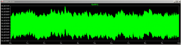
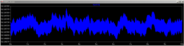
Yes it was an eye opener for me as to just how much difference CRCRC made to the ripple. As you say though low current. Even with a very modest current draw (the sim output above is 250mA) the voltage drop is quite significant. The higher the current the bigger the drop. the difference between having or not having R2/R4 is about 1.5V pre reg in the above sim.
I ended up using a 15-0-15 toroidal for my +/- 10V output. The main reason for this was I wanted to have at least 5V difference in to out. This is another area that makes a difference to the final output performance.
Any less than 5V difference in to out and the ripple increases on the output. I don't think it is a coincidence that all of the data sheet measurements showing ripple rejection are with 5V in to out differential
So it is a bit of a balancing act. If you have too much voltage drop to reduce the ripple pre-reg, you may end up with worse ripple on the output if the in - out differential drops below the 5V threshold.
Tony.
Last edited:
Yes, current draw is significant with series resistors.
What you could try is using lower value resistors on the simulation and tests, and see if ripple is affected (increased) for what value. I think you could go down to 1R2 with no problems.
Also, yes, the 3X7 needs more input voltage than other regulators to perform better. Which is not something that is not mentioned often.
Hi Tony,
Haven't forgotten the Xover project, just being slow!
If you reduce the ripple CRCRC to the simpler C-R-C and then add a simple C multiplier, you can radically change the sound of this simple reg - sort of like a reversed Teddy-Reg (Pink Fish Media) - will suck up another volt or 2, but this is quite manageable.
Curiously, both Patrick (EUVL) uses simple single pole reg for his balanced F5 power supply and John Brown (EC Design) has used a rather sophisticated combination for his newest power supply for the 1541A dac chip power supply - interesting!
Hi Jh, no I haven't forgotten I'm just very slow!!! Now that this is built it is time to start breadboarding the Synergy This was the pre-requisite. It was my goal to have both done before the end of 2011, unfortunately I only got one done. Hopefully the synergy will be a bit quicker now
Tony.
This was the pre-requisite. It was my goal to have both done before the end of 2011, unfortunately I only got one done. Hopefully the synergy will be a bit quicker now Tony.
Hi Zack, R12 and R13 are to provide a minimum current draw for the reglulator. The reason there are two is because it was easier for me to get 1/2 w resistors than 1W ones, and I didn't want them getting too hot. I'm pretty sure it was Jan Didden that said that LM317's performed better with a certain amount of current draw, but I can't find the reference. The idea for the resistors is to provide a minimum constant draw of around 40mA to ensure the reg stays in a better performance zone.
Tony.
Tony.
Everyone seems intent on getting the noise level from the supplies down to less than zero.
However, in Hi-End Hi-Fi use I personally can't hear any noise from the humble LM317.
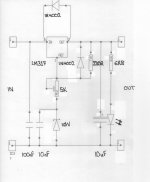
In my simple circuit I simply wanted 18V at about 20mA for a Pre-Amp.
The results are an Audio Blackness (SILENCE) that I can not see any point in bettering.
Point of note - anyone wishing tio try this circuit, please insert a 1K in series with R2 (without it there is a danger of frying the zener if R2 is adjusted to its minimum).
Maybe I've just got everything right and the Pre has a high PSRR. But why make it any better than it already is ?
Incidentally the LED is there to increase the output current to approx 25mA, as well as to serve as an indicator.
However, in Hi-End Hi-Fi use I personally can't hear any noise from the humble LM317.
In my simple circuit I simply wanted 18V at about 20mA for a Pre-Amp.
The results are an Audio Blackness (SILENCE) that I can not see any point in bettering.
Point of note - anyone wishing tio try this circuit, please insert a 1K in series with R2 (without it there is a danger of frying the zener if R2 is adjusted to its minimum).
Maybe I've just got everything right and the Pre has a high PSRR. But why make it any better than it already is ?
Incidentally the LED is there to increase the output current to approx 25mA, as well as to serve as an indicator.
Attachments
fair comment KatieandDad I think SY commented in my experiments and measurements thread that at some point it ceases to be about improving anything audibly and becomes solely an exercise in engineering.
Obviously some circuits will have better PSRR than others. I took the approach if it's not there then it can't cause a problem I did say it was overkill
Tony.
I think SY commented in my experiments and measurements thread that at some point it ceases to be about improving anything audibly and becomes solely an exercise in engineering. Obviously some circuits will have better PSRR than others. I took the approach if it's not there then it can't cause a problem
I did say it was overkill Tony.
The upper 1n400x caters for back emf bypass when the transformer shuts down. Keep it.
The lower 1n400x caters for back emf when the regulator shuts down and is needed to discharge the cap smoothing the ADJ pin. 10nF does not require that extra diode protection to be added. 100uF across the Zener would require the extra diode.
The voltage from OUT to ADJ (if the regulator is not broken) is ~ 1250mV.
The current from OUT to Zener cannot exceed 1250mV/220r ~ 5.7mA
The worst case dissipation in the Zener is ~ 57mW.
In normal stop start run operation no setting of the 5kVR can damage the Zener.
@ 18V output the 6k8 has ~ 16V across it. The current passing to the LED is ~ 2.4mA
The total demand from the OUT PIN is ~ 2.4mA + 5.7mA + load current. The load current must equal or exceed 16.9mA at all operational conditions for the 25mA desired REG load to be true.
Last edited:
The upper 1n400x caters for back emf bypass when the transformer shuts down. Keep it.
The lower 1n400x caters for back emf when the regulator shuts down and is needed to discharge the cap smoothing the ADJ pin. 10nF does not require that extra diode protection to be added. 100uF across the Zener would require the extra diode.
The voltage from OUT to ADJ (if the regulator is not broken) is ~ 1250mV.
The current from OUT to Zener cannot exceed 1250mV/220r ~ 5.7mA
The worst case dissipation in the Zener is ~ 57mW.
In normal stop start run operation no setting of the 5kVR can damage the Zener.
@ 18V output the 6k8 has ~ 16V across it. The current passing to the LED is ~ 2.4mA
The total demand from the OUT PIN is ~ 2.4mA + 5.7mA + load current. The load current must equal or exceed 16.9mA at all operational conditions for the 25mA desired REG load to be true.
WAFFLE-WAFFLE-WAFFLE.
It works and the design is perfect, other than the possibility of damaging the zener without the extra resistor with R2.
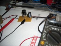
I used this to replace the Shuntkys while I was trying to get my Pumpkins to work.
Do bear in mind that my load has over 30000uF in it and draws over 20mA in its own right.
Last edited:
There were two areas that were proposed here to improve and the reason for this topic:
1) The adjustment pin arrangement, where a transistor was added.
2) The output capacitor, where a resistor was added in series with it.
The 3X7s do not seem to like low-esr capacitor types, and the series resistor corrected that, allowing using any cap.
OTOS the 3X7s do not like too much capacitance, so if you are using 30,000uF as you say you are, that would go against many people that think otherwise.
Regardless. It works beautifully.
You can go only so far with theory then practicality takes over.
There is a 1R5 in series with the supply which might make a difference.
Things working beautifully may just mean that it's just doing its primary job:regulate
But I think what we are trying to do here is make things better. By that I mean "sound better". Which is hard to prove because it's mostly a subjective thing.
Theory is what this topic started to do and DIY by definition means make things practical.
If you are putting a series resistor after the regulator, you're probably invalidating one of the important objectives, which is lowering impedance.
One of the first thing that was done in CD player mods in the '80s was just eliminate every series resistor after regulators that manufacturers insisted to put.
.It really is worth using a current in between Vout and ADJ since the variation of the 1.25 volt reference in the regulator IC is the main contributor to PSRR and output impedance degradation. I have a circuit that should work pretty well with easily available parts. The transistors can be any thing with a very high Hfe at a milliamp or two. C1 should be a film cap and you can get away with something like 1uF if you what. I believe the voltage out is about 15 volts for the resistor values shown. I also have another design with a current jfet and a diode thermally coupled to the regulator with copper tape. The thermally coupling and the likely hood that you don't have a jfet CCS in your parts box may make this an easier circuit. You could get rid of Q1 and Q2 and put a resistor across Vout to ADJ but the performance of the circuit is not as good as with the current source.
Please, put here circuit of "another design with a current jfet and a diode thermally coupled to the regulator with copper tape".
.
Thanks.
- Home
- Amplifiers
- Power Supplies
- Improving the LM3x7 regulator circuit