SCOPE OUTPUT NUMBER 2
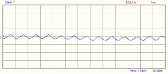
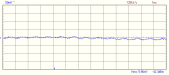
Now the output was set to 3mV 1kHz. Notice there's a drift and it shows 0.3dbm.
Does this lead to any conclusion?? As I see, the output seems OK even at low oscillator levels, and maybe the problem lies in the oscilator, right?
Now the output was set to 3mV 1kHz. Notice there's a drift and it shows 0.3dbm.
Does this lead to any conclusion?? As I see, the output seems OK even at low oscillator levels, and maybe the problem lies in the oscilator, right?
Attachments
Regaring the caps...
The PS uses 4 1000uF/35V caps and a few smaller ones (you can see them on page 8-23).
I have on hand:
ELNA Cerafines 1000uF/35V
Panasonic FM 1200uF/35V
ELNA SILMIC II 1000uF/35V
Demian, do you know in which page the ripple numbers are located? I couldnt find them at all.
The PS uses 4 1000uF/35V caps and a few smaller ones (you can see them on page 8-23).
I have on hand:
ELNA Cerafines 1000uF/35V
Panasonic FM 1200uF/35V
ELNA SILMIC II 1000uF/35V
Demian, do you know in which page the ripple numbers are located? I couldnt find them at all.
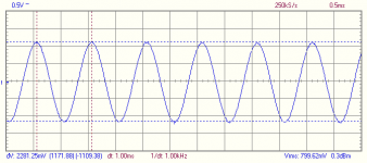
OSCILLATOR OUTPUT 10mV
Here is the output of the internal oscillator set to 10mV and 1kHz. Im no expert, but to me, doesnt look good. The wave keeps 'oscilalting' on my screen, as if there was another lower frequency behind it. My spectrum analyzer says 260Hz.

Here is the output of the internal oscillator set to 10mV and 1kHz. Im no expert, but to me, doesnt look good. The wave keeps 'oscilalting' on my screen, as if there was another lower frequency behind it. My spectrum analyzer says 260Hz.
Attachments
This is the real last one....
I just found out a few more things...
1-Even at 3V and 1kHz there are lots of 260Hz coming from somewhere.
2-Noise is definitely higher at lower levels, according to my spectrum analyzer.
3-It looks like theres a cover missing inside my unit. I just noticed that the oscillator part has a top cover, but mine seems to be missing the bottom one. This could be causing number 2.
Hi bsgd,
Replace the original capacitors with any brand of good quality capacitors of the same capacitance. Going up to 50 V, or 63 V parts will be closer to the original size and the tahn will be lower.
Given the age, just simply replace the capacitors, same for the smaller electrolytic capacitors.
Not terribly surprising if you think about it. As your signal level drops, circuit noise will make up a larger percentage of the signal. I have no way to know if it is normal or not as far as the values are concerned.
Now for the more interesting problem. Where on earth is 260 Hz coming from? Check all signal amplifier stages. Open capacitors will cause them to become unstable and they make simply be oscillating. Again, not terribly surprising here.
The advice Demain has given you is right on the money. Forget everything you have read on improving audio circuits. Your job is to preserve this instrument as close to the original design as you can. Only once you have it operating properly should you consider changing anything.
Hi Demain,
Hi Jack,
Shipping that here is completely out of the question though!
-Chris")
Replace the original capacitors with any brand of good quality capacitors of the same capacitance. Going up to 50 V, or 63 V parts will be closer to the original size and the tahn will be lower.
Given the age, just simply replace the capacitors, same for the smaller electrolytic capacitors.
Okay, now that is a problem. All the shields must be in place. The good news is that you can make one close enough if you can bend metal. A home brew shield beats the heck out of a missing one.It looks like theres a cover missing inside my unit. I just noticed that the oscillator part has a top cover, but mine seems to be missing the bottom one.
Not terribly surprising if you think about it. As your signal level drops, circuit noise will make up a larger percentage of the signal. I have no way to know if it is normal or not as far as the values are concerned.
Now for the more interesting problem. Where on earth is 260 Hz coming from? Check all signal amplifier stages. Open capacitors will cause them to become unstable and they make simply be oscillating. Again, not terribly surprising here.
The advice Demain has given you is right on the money. Forget everything you have read on improving audio circuits. Your job is to preserve this instrument as close to the original design as you can. Only once you have it operating properly should you consider changing anything.
Jump the oscillator output to the analyzer input. At 100% THD, you can monitor your oscillator in normal THD mode. You can also remove some of the fundamental to see the residuals more clearly. The noise and harmonics will be amplified for you as you decrease your reference levels (reduce the full scale dB in THD mode). You could also simply hang your 'scope on the oscillator output across your load resistor. Either way, you can monitor the signal. I do this all the time. The oscillator level position on the function switch is normally only used to set your output level. The monitor output will always show you the output of the filter section in normal distortion mode.I tried to scope the monitor output of my HP, but, set to the OSCILLATOR LEVEL function, the output is disabled.
Hi Demain,
I agree. Very unusual and very apt to increase distortion at higher power levels. Bsgd, does that fuse appear to be factory, or added? To tell you the truth, I have not noticed if this was a normal part of this instrument.its unususal to even have a fuse on the monitor output.
Don't you find that the dielectric dissipation for higher voltage ratings improves? The smaller parts (if still good) may be superior to the new capacitors. I'd rather do that to arrive at close to the same size of case.Same value or a little larger in the same footprint.
Hi Jack,
Oh, I wish I could pick that up!! I have an older calibrator I could use that with. Mind you, a Fluke 5700A or Fluke 5500A with scope option, or 5520A would make me one happy camper! I think my present calibrator is an RFL or something like that. It's only good for cheaper 3 1/2 digit multimeters. Mind you, I can use it as a transfer standard with my existing equipment.I have a Fluke 5205A Amplifier which I am willing to give away to anyone who will pay the shipping (or pick up). I think it fell on its head, however. Uses a pair of 120V lines.
Shipping that here is completely out of the question though!
-Chris
I haven't looked inside my analyzer in a while, but a lot of this kind of thing has internal shields referenced to some specific ground or circuit point. You definitely have to make something up, but be sure it only contacts where the original did, and doesn't short to the chassis unless it's supposed to.
bsgd said:[snip]1-Even at 3V and 1kHz there are lots of 260Hz coming from somewhere.[snip]
Could it be 240Hz? Harmonic of the 60Hz line, coming in from supply ripple? Not unusual with a) low signal level and b) missing screen cover.
jd
Hi Demain,
I agree. Very unusual and very apt to increase distortion at higher power levels. Bsgd, does that fuse appear to be factory, or added? To tell you the truth, I have not noticed if this was a normal part of this instrument.
Don't you find that the dielectric dissipation for higher voltage ratings improves? The smaller parts (if still good) may be superior to the new capacitors. I'd rather do that to arrive at close to the same size of case.
-Chris [/B][/QUOTE]
I need to check the schematic to see where the fuse is. It may be in the ground to prevent expensive mistakes. Since the monitor is hi Z then I doubt there would be any effect on the signal.
New caps will probably be much better in many ways than the originals. You don't want to make them much bigger in value or the peak ripple current will be a problem. The higher temp caps will have a longer service life, probably more important than lower dissipation here, since once fixed you would want to just leave it and use it. Higher voltage is fine as long as the operating voltage is at least nearly 1/2 the rated voltage or the cap value may degrade over time.
I have an Optimation AC calibrator. Really interesting design and something to learn tricks for performance from. But really old. It has an amplifier module for the 100V output with a .1% spec to 1 MHz, all solid state from 1970 or so. Many analog problems solved to make precision AC (6 digits and accurate). The uncertainty however is greater than I want to deal with. Its also quite large.
Trying to get some confidence in measurements can lead down interesting paths. An accurate volt, ohm and frequency reference is a major hurdle. There is a guy on eBay selling a volt reference kit. Its a good value and at .01% (I think) better than most hobbiest requirements. After years of wondering how to get a decent frequency reference (Cesium standards are not cheap) I discovered GPS disciplined oscillators. For less than $200 on ebay you can get 10 MHz at better than 1 ppB. Thats good enough for anything I'm doing. I also got some thermal transfer standards and discovered that even NIST can't measure AC better than .002%. But I can ensure that the oscillator response is flat.
I agree. Very unusual and very apt to increase distortion at higher power levels. Bsgd, does that fuse appear to be factory, or added? To tell you the truth, I have not noticed if this was a normal part of this instrument.
Don't you find that the dielectric dissipation for higher voltage ratings improves? The smaller parts (if still good) may be superior to the new capacitors. I'd rather do that to arrive at close to the same size of case.
-Chris
[/B][/QUOTE]I need to check the schematic to see where the fuse is. It may be in the ground to prevent expensive mistakes. Since the monitor is hi Z then I doubt there would be any effect on the signal.
New caps will probably be much better in many ways than the originals. You don't want to make them much bigger in value or the peak ripple current will be a problem. The higher temp caps will have a longer service life, probably more important than lower dissipation here, since once fixed you would want to just leave it and use it. Higher voltage is fine as long as the operating voltage is at least nearly 1/2 the rated voltage or the cap value may degrade over time.
I have an Optimation AC calibrator. Really interesting design and something to learn tricks for performance from. But really old. It has an amplifier module for the 100V output with a .1% spec to 1 MHz, all solid state from 1970 or so. Many analog problems solved to make precision AC (6 digits and accurate). The uncertainty however is greater than I want to deal with. Its also quite large.
Trying to get some confidence in measurements can lead down interesting paths. An accurate volt, ohm and frequency reference is a major hurdle. There is a guy on eBay selling a volt reference kit. Its a good value and at .01% (I think) better than most hobbiest requirements. After years of wondering how to get a decent frequency reference (Cesium standards are not cheap) I discovered GPS disciplined oscillators. For less than $200 on ebay you can get 10 MHz at better than 1 ppB. Thats good enough for anything I'm doing. I also got some thermal transfer standards and discovered that even NIST can't measure AC better than .002%. But I can ensure that the oscillator response is flat.
Hi Demian,
A fuse in monitor out might make perfect sense if you did float the analog section up. That is one feature these instruments have, and could prove to be a disaster on the bench if you were to forget about that. I use the ground lift to reduce noise with some equipment.
If you can give me some pointers, I'd be very grateful. I am currently using a pair of Data Precision 8200 for references. I think it's going to be rebuild time soon though (trim controls and power supplies). I have no AC references except using a 3457A or 34401A as a transfer reference.
-Chris
Oh, is that in the monitor leg? I was thinking we were talking about the oscillator output (at 600 ohms). High signal levels of a couple volts may really kill the intrinsic low THD at the 0.0018% level in that case. Monitor out might see a 1 M load from a 'scope, at least that is what hangs off of mine. It's also buffered I think, so it will not affect anything. I'll have to see if loading mine down does anything. I can honestly say that I've never done that.Since the monitor is hi Z then I doubt there would be any effect on the signal.
A fuse in monitor out might make perfect sense if you did float the analog section up. That is one feature these instruments have, and could prove to be a disaster on the bench if you were to forget about that. I use the ground lift to reduce noise with some equipment.
100% with you on that, but I don't think the 105° caps last any longer. This equipment does not get that warm inside. The originals were the normal types to begin with. If you are working on something that is warm, then 105° types are definitely the way to go.You don't want to make them much bigger in value or the peak ripple current will be a problem.
The only thing I have that runs all the time is the ox in my 5335, it's an oven type oscillator. Everything else settles down within 1/2 hour for sure. High precision references must obviously be left on all the time, battery backup helps here.since once fixed you would want to just leave it and use it.
That's excellent!Many analog problems solved to make precision AC (6 digits and accurate).
If you can give me some pointers, I'd be very grateful. I am currently using a pair of Data Precision 8200 for references. I think it's going to be rebuild time soon though (trim controls and power supplies). I have no AC references except using a 3457A or 34401A as a transfer reference.
Yes, no questions there.Its a good value and at .01% (I think) better than most hobbiest requirements.
Demian, that is my current dilemma. I could certainly use some pointers. I want to use a GPS based unit, and WWV 10 MHz for backup. My plan is to build a 10 MHz amplifier with a wide range AGC. I was going to use 10 MHz xtals as filters and simply amplify it through, then an IC to reduce the jitter and buffer the outputs to several BNC connections. Everything then will run off the same clock. The GPS source would be the master and I do have a voltage controlled crystal oscillator. I just need to store the correction voltage and monitor phase. A Microchip controller might work well here. Problem is that I don't really know what I'm doing. I just have a good (I hope) idea.After years of wondering how to get a decent frequency reference (Cesium standards are not cheap) I discovered GPS disciplined oscillators.
-Chris
Chris,
The best replacement caps I have IMO are the PANASONIC FM 1200uF 35V 105C. Would they be OK? I dont have any higher voltage at 1000uF or so.
A new aluminum DIY shield is in place already.
I will check all caps and try to find the source of the 260Hz noise and get back to you.
At last, what I did was exactly that, connected my scope across the 680R load. You can see the output on my posts on page 5 of this thread.
Conrad,
I did take care to reference my shield to the same ground, making sure there was no short anywhere.
jd,
Could be 240Hz, I'll have to check again since now I have the shield in place.
Demian,
The fuse is factory original, and can be seen on the schematics in the service manual. The actual fuse inside the unit is still the original one.
As I said to Chris, the best replacement IMO for the caps are the Panasonic FM 1200uF 35V 105C. All the other I have are only 85C, and maximum 35V.
Hi Jack,
Thank you very, very much for that link!
Now it's my job to get smarter! The site looks like an excellent source for information and it does seem to cover what I want to do. So, it's now bookmarked.
Of course, I did go out and buy some things before I knew what I was doing. I also bought an oven controlled oscillator for another backup. Just shows you that questions asked here are of great value, and I jumped the gun - again.
-Chris
Hi bsgd,
Forget everything you have heard in audio circles. It's all for naught, just stick with good quality industrial parts and you will have done an excellent job.
Let's put it another way. Say, you have had these Panasonic capacitors for two years on the shelf. Freshly manufactured Sprague or United Chemicon would be better. Same for fresh Panasonic at 85°. There is no magic going on here at all. Just a good design using good parts.
Happy hunting!
-Chris
If the capacitance is the same, or close (like 200 uF higher as yours are), just use them. Any, and I really mean any good quality capacitors will work just fine here. Even 85° Cornell Dublier of new manufacture would be excellent replacements.The best replacement caps I have IMO are the PANASONIC FM 1200uF 35V 105C.
Forget everything you have heard in audio circles. It's all for naught, just stick with good quality industrial parts and you will have done an excellent job.
Let's put it another way. Say, you have had these Panasonic capacitors for two years on the shelf. Freshly manufactured Sprague or United Chemicon would be better. Same for fresh Panasonic at 85°. There is no magic going on here at all. Just a good design using good parts.
Excellent!A new aluminum DIY shield is in place already.
Don't focus too quickly. It may not be a capacitor problem, so keep an open mind and follow the clues.I will check all caps and try to find the source of the 260Hz noise and get back to you.
Happy hunting!
-Chris
Anatech:
I have spent too much time reading the time-nuts mail list. They are as far out there as us audio nuts.
Trying to receive the WWV 10 MHz signal won't work well. the ionosphere causes too much dispersion. The Thunderbolt is the way to go. There are two guys selling them from China. Get the kit w/ supply and antenna. Its very hard to improve on.
AC references turn out to be elusive. Its the nature of AC. A better transfer standard is an AC-DC thermal transfer. You can get an old Fluke pretty cheap since no one wants them. And DC is a better place to start from. The ac-dc transfer standard is also a really good test for response flatness.
The 105°C caps have a different and far less volatile electrolyte and are supposed to last a lot longer (or so the rep told me).
bsdg:
The 240 Hz is interesting. it 60 Hz * 4 so its unusual to be strong from the supply. Thats almost always 120 Hz. What readings to you get with the input shorted? Does the low pass filter change them?
Looking at the schematic the fuse connects in the signal lead back to the output of a buffer ammp that drives a true rms converter. There are a pair of back to back caps in series as well. I would check the buffer and its also possible that the trms chip is damaged or it needs adjustment. I can't see any other way the fuse may get blown. There are also a pair of Zeners clamping the signal to ground at that node. This stuff is all on pages 8-19/8-20.
There are also some good test points for checking the signals on that page.
anatech said:Hi bsgd,
If the capacitance is the same, or close (like 200 uF higher as yours are), just use them. Any, and I really mean any good quality capacitors will work just fine here. Even 85° Cornell Dublier of new manufacture would be excellent replacements.
Forget everything you have heard in audio circles. It's all for naught, just stick with good quality industrial parts and you will have done an excellent job.
Let's put it another way. Say, you have had these Panasonic capacitors for two years on the shelf. Freshly manufactured Sprague or United Chemicon would be better. Same for fresh Panasonic at 85°. There is no magic going on here at all. Just a good design using good parts.
Don't focus too quickly. It may not be a capacitor problem, so keep an open mind and follow the clues.
Happy hunting!
-Chris
OK, Im trying to get all these audio mumbo jumbo from my head
I'll use the Panas as they are the best caps , and the ones I most recently bought. Their capacitance is only 200uF more than the originals, that, by the way, dont seem to be from any respected brand.
I may need some help to hunt down the noise, but then, I'll post here as I try to figure out whats going on.
1audio said:
bsdg:
What readings to you get with the input shorted? Does the low pass filter change them?
Looking at the schematic the fuse connects in the signal lead back to the output of a buffer ammp that drives a true rms converter. There are a pair of back to back caps in series as well. I would check the buffer and its also possible that the trms chip is damaged or it needs adjustment. I can't see any other way the fuse may get blown. There are also a pair of Zeners clamping the signal to ground at that node. This stuff is all on pages 8-19/8-20.
There are also some good test points for checking the signals on that page.
I'll check that out tonight and post back what I get. I didnt try the inputs shorted or the LP filter yet.
If you get a Fluke thermal transfer standard, you'll probably wind up getting several standard cells. These have to be kept "quiet" --
I also have a Fluke 3330B D.C. standard with GPIB -- I don't bother with the GPIB on this one. This was an invaluable device for the work I did designing a microprocessor controlled tube-tracer. It will do a kiloVolt at 100mA. It is also accurate to 7 places, but I don't have an HP3458 I guess that's something like 2^20th.
You can often find HP equipment -- like a 5328 counter or 3586 receiver with an ovenized 10MHz reference -- used to be that the sellers didn't realize that this was the best part of the entire device.
Hi Jack,
Nope. I don't want to play with standard cells at all. Just getting them here will shift their voltage. No interest there from me.
Often enough, my needs for an AC voltage measurement ends up being a relative one. So many dB up or down. Small errors will not affect that, and the HP 34401A is overkill. Would I like an HP 3458A? Absolutely! I used one for a while in the lab. Fluke has an upgraded reference for this meter as well, or they did unless Agilent improved the reference. They probably have.
For important measurements, I change the filter freq. and number of averages on the 34401A and 3457A, so I get a repeatable number that way. Most people with these may not even understand how to do that. The times I need to do this are far and few between and I end up refreshing my memory by reading the owner's manual.
Hi Demian,
What I have found is that the newer capacitors tend to test less well than the equivalent older part. However, if you select a new capacitor rated for a higher voltage with the same size of can as the older one, they measure about the same for dissipation. Interesting - no?
Thank you both (Jack and Demian) for your suggestions. I feel that with your help, I have a direction to follow that makes some sense.
-Chris
Nope. I don't want to play with standard cells at all. Just getting them here will shift their voltage. No interest there from me.
Often enough, my needs for an AC voltage measurement ends up being a relative one. So many dB up or down. Small errors will not affect that, and the HP 34401A is overkill. Would I like an HP 3458A? Absolutely! I used one for a while in the lab. Fluke has an upgraded reference for this meter as well, or they did unless Agilent improved the reference. They probably have.
For important measurements, I change the filter freq. and number of averages on the 34401A and 3457A, so I get a repeatable number that way. Most people with these may not even understand how to do that. The times I need to do this are far and few between and I end up refreshing my memory by reading the owner's manual.
Nice, that's what I use the Data Precision 8200 for. They are not as accurate I don't think, but then I always monitor the output voltage and use that number. I think I'll start using the GP1B port though. The switches are dirty - again.I also have a Fluke 3330B D.C. standard with GPIB
Mine is both not working and has a standard oscillator. My 5335A has an ovenized oscillator, I'll have to check the 8901A receiver to see what it uses.3586 receiver
Well, they do now ...used to be that the sellers didn't realize that this was the best part of the entire device.
Hi Demian,
That was one of my concerns. We used to be able to listen to it way back when I was in high school. I still live close by (50 miles maybe), but at a higher elevation than the school was. I figured it was worth an attempt, the parts can be reused if it doesn't work out.Trying to receive the WWV 10 MHz signal won't work well. the ionosphere causes too much dispersion.
My experience does not support that. It's interesting to note that several older capacitors test beautifully still after 30 years or more in service. They are sealed on the bottom, over the rubber, by a hard coating. Epoxy may achieve the same effect. Basically, the electrolyte is not allowed to wick out I guess. Food for thought.The 105°C caps have a different and far less volatile electrolyte and are supposed to last a lot longer (or so the rep told me).
What I have found is that the newer capacitors tend to test less well than the equivalent older part. However, if you select a new capacitor rated for a higher voltage with the same size of can as the older one, they measure about the same for dissipation. Interesting - no?
Curiosity and interest conspire to doom me to the same fate you suffered as well. I am looking forward to getting something working I can depend on. Next on the list after this is a distribution amp for my clock signal. I already have a bunch of 50 ohm terminators ready.I have spent too much time reading the time-nuts mail list.
Thank you both (Jack and Demian) for your suggestions. I feel that with your help, I have a direction to follow that makes some sense.
-Chris
I've got a Data Precision 8200 as well, and those #%*(!$@* switches! Once a year or so I have to open it up and flood the switches with Caig DeOxit. That's the best stuff I've found. Other than that it's a very solid unit. I've also got the Fluke 1KV boat anchor standard (332B ? can't remember). Too big, too heavy- free to a good home if anybody wants it, but pick up only.
WWV isn't a practical frequency standard, but WWVB (60kHz) is excellent. It's easy to build a receiver for, then you can lock a 6MHz oscillator and divide as needed.
CH
WWV isn't a practical frequency standard, but WWVB (60kHz) is excellent. It's easy to build a receiver for, then you can lock a 6MHz oscillator and divide as needed.
CH
- Status
- This old topic is closed. If you want to reopen this topic, contact a moderator using the "Report Post" button.
- Home
- Design & Build
- Equipment & Tools
- Improving older test equipment