Here it is: the transistor versions have the usual negative tempco, and the LED one has a positive one because the LED compensates the Vbe, but since the current density in the LED is much smaller than in the transistor, there is a large overcompensation.What about temperature dependence?
For other LED types, the degree of compensation could be quite different.
Also included is the stability of the output current vs. output voltage (output impedance).
The transistor versions are very similar, the LED one is significantly worse (because there is only one transistor to provide loop gain).
Note that when the improved version is wired for two-terminal (V1=V2), the compensation can be tailored to also cancel the output impedance, see above.
Attachments
Last edited:
How does the current source that Sy uses in his Heretical preamp fare compared to these?
Schematic?
Schematic?
He's got it on his page here:
SYclotron Audio The Heretical Preamp, part 2
(Great design BTW, the input transformer is a great but underutilized advantage to most line stages, I'm using one of this buffer right now, dead silent and very stable into 10k)
Last edited:
Here is the comparison:
The PSSR of the improved circuit is vastly superior.
On the output impedance, they perform very similarly, but SY's version has a small advantage.
If the improved version is equipped with a cascode, things reverse again: the current variations become vanishingly small, while the PSRR remains unchanged.
Attachments
Elvee,
a simple JFET CCS vastly outperforms all variants you have invented. You have been wasting your time since 3rd September 2010.
Don't discourage him Please

Obviously not, but they all obey the same laws of semiconductor physics applied to junctions,
There is something about this line that I like
Elvee,
a simple JFET CCS vastly outperforms all variants you have invented.
Post the circuit Lumba.
Elvee,
a simple JFET CCS vastly outperforms all variants you have invented. You have been wasting your time since 3rd September 2010.
Are you that sure?
Besides, if you require 50mA and/or 500V, a jFET might be unpractical.
Attachments
Do you mean vs. temperature?can you compare stability?
Here is an example for a 10V step, rise time 100ns (=100V/µs).What about seeing reports for a step response?
Vary the V/ns of the change in step response.
Note that the transistors are low frequency types with relatively large collector capacitances. A small BFxxx could improve that aspect, if it is of great importance.
The cascoded version would perform even better.
Attachments
Elvee,
You are toiling with irrelevant aspects.
You got absolutely no reason for doubt.Are you that sure?
50mA can be difficult with JFETs, but is easy with some other kind of FET.Besides, if you require 50mA and/or 500V, a jFET might be unpractical.
You are toiling with irrelevant aspects.
Did you even look at the pic of message #32? Do you know what it means?Elvee,
You got absolutely no reason for doubt.
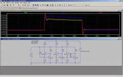
Here it is, but don't jump to conclusions.Hi,
as I suspected, the feedback CCS has ripple and more variation when pulsed signal is applied.
Can you do this for all the variations so far. and can you expand the area for easier observation.
This kind of test has to be taken with a pinch of salt, especially in simulation: amongst other things, the transition from the flat part of the waveform to the slope is instantaneous, which is not possible in reality.
For example, the blue trace appears to have severe ringing, but if you look at the time scale, you'll see that the ringing occurs at over 100MHz.
This kind of ringing can be killed easily with a small series resistance somewhere, or with a minimal bypassing.
The impedance vs. frequency curve is probably more significant to appreciate the differences between the versions, and I'll show some examples.
One interesting thing is that the usual precaution of using a base stopper in the feedback versions can be counter-productive.
Attachments
Interesting results so far.
I have another thing to throw in: A small cap between the bases of the feedback version. What do you think about this idea? (it wasn't mine but I used it in an amp) I don't like the overshoot somehow and the rounded corner looks more friendly to me... Is this any good?
I have another thing to throw in: A small cap between the bases of the feedback version. What do you think about this idea? (it wasn't mine but I used it in an amp) I don't like the overshoot somehow and the rounded corner looks more friendly to me... Is this any good?
Attachments
- Home
- Amplifiers
- Solid State
- Improved current source/sink