I still remember two issues of the German magazine "elrad" with approaches to improving the characteristics of current sources:
1) Issue January 1988 page 47 - go to Fig. 3 under
https://www.elektronik-kompendium.de/public/schaerer/curr2pol.htmfor the circuit diagram
2) CCS as LED versions (two different approaches). Unfortunately I know only the German title of the article:
"LEDs - zum Leuchten viel zu schade" any issue between 1986 and 1989
Maybe one of the members know the associated issue and can upload the article.
One of this both approaches are to find in Fig. 7 under
https://www.elektronik-kompendium.de/public/schaerer/currled.htmBut the other - from my view better approach I don't find on the web.
Attachments

Last edited:
The CCS² approach (another CCS to stabilize the bias current of the main CCS) does work, of course, like any brute-force method, but it is possible to use the simple resistor trick, AND get better better results, for both DC/LF and HF frequency ranges.One of this both approaches are to find in Fig. 7 under
https://www.elektronik-kompendium.de/public/schaerer/currled.htm
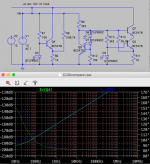
The green trace is the plain-vanilla, LED-based CCS.
The yellow trace is the double-barrelled CCS: an improvement of almost 30dB is visible.
But the clear winner is the simpler, compensated CCS: red trace. It affords another 30dB improvement, and remains better than the two other options, even at higher frequencies.
More is not always better......
Attachments
Have you tested a real circuit? I don't trust simulations.But the clear winner is the simpler, compensated CCS: red trace. It affords another 30dB improvement, and remains better than the two other options, even at higher frequencies.
But that performance is exquisitely sensitive to the value of the compensating resistor, so its not really practical requiring S.O.T. during manufacture to get that performance (and I suspect the emulation is missing some important parameters like temperature drift that will scupper that performance anyway).But the clear winner is the simpler, compensated CCS: red trace. It affords another 30dB improvement, and remains better than the two other options, even at higher frequencies.
I experimented with the compensated version above, and a more complex scheme I devised with a voltage reference and cascode.
My version took compensation from the voltage reference to be more independent of supply hopefully.
I carefully tuned the compensation resistors by hand for best performance.
The first plot has the supplies commoned, probably the more normal use-case for a CCS:

And with separate supplies:

Clearly the commoned supplies sees the limitations of bandwidth of the output device (Miller effect I presume), since its got a varying load to deal with. I'm a bit surprized the cascode doesn't help somewhat though.
In the separated case its possible to improve on the compensated version with extra stabilization of the voltage, but this only becomes visible due to the loading effects on the CCS being ignored. If you assume constant load voltage you might as well set current with a resistor!!
My version took compensation from the voltage reference to be more independent of supply hopefully.
I carefully tuned the compensation resistors by hand for best performance.
The first plot has the supplies commoned, probably the more normal use-case for a CCS:
And with separate supplies:
Clearly the commoned supplies sees the limitations of bandwidth of the output device (Miller effect I presume), since its got a varying load to deal with. I'm a bit surprized the cascode doesn't help somewhat though.
In the separated case its possible to improve on the compensated version with extra stabilization of the voltage, but this only becomes visible due to the loading effects on the CCS being ignored. If you assume constant load voltage you might as well set current with a resistor!!
Attachments
I have used it, but in practice the level of compensation realistically available is ~20 - 30dB if you don't want to tune each circuit individuallyHave you tested a real circuit? I don't trust simulations.
Yes, the sim is only valid for very restricted conditions, which are not realistically achievable in practice.But that performance is exquisitely sensitive to the value of the compensating resistor, so its not really practical requiring S.O.T. during manufacture to get that performance (and I suspect the emulation is missing some important parameters like temperature drift that will scupper that performance anyway).
But with a single resistor, it remains possible to match or exceed the performance of a circuit twice as complex, which is not to be scorned at
It is probably just the Cbc capacitance of the transistor, without Miller effect since the base sees the low impedance of the referenceI'm a bit surprized the cascode doesn't help somewhat though.
So if you're not a fan of this compensation technique, what CCS circuit would you recommend? I've been looking at the datasheet for the current regulating diodes from Central Semiconductor, they look pretty interesting... but pricey.But that performance is exquisitely sensitive to the value of the compensating resistor, so its not really practical requiring S.O.T. during manufacture to get that performance (and I suspect the emulation is missing some important parameters like temperature drift that will scupper that performance anyway).
What matters is the noise current it injects, and since it is highish, the current is very low and does not matter.
The compensation trick works well, and improves most types of CCS by >20dB, almost for free, so it's worth using. If you are prepared to tweak the circuits individually, 40dB is reachable.
Here are other CCS ideas, 2-wire version:
https://www.diyaudio.com/community/threads/improved-2w-current-sources-ii.197104/post-2720209
- Home
- Amplifiers
- Solid State
- Improved current source/sink