then again, I am very happy the way it sounds right now, I may never get there...")
Great! Please, please enjoy your amp and music - and cherish what you have already achieved. Put a sticker on - "I did this!"
That feeling is worth more than any further sub-dB improvement you may be able to achieve.
Unless of course that you've already been fatally bitten by the MOD bug and soon wonder "what if I changed........."
You'd be doomed, but we would welcome you into the club!
Per
LOL! I was just wondering about that the other day, am I doomed with this hobby, am I addicted to this hobby that bad already? and I think I am! as when you learn something new and you know you can apply it someplace else, the light bulb just goes off, as I have learned quite a lot from all of you here, on this great site, in the last couple of years.
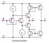
and talking about learning, I was reading the other day about 'Diamond Buffers' topology, have any of you have experience with that topology, does it sound better or different as some say ?
who knows, but that is the problem, there's always something to be discovered with this hobby.
as when you learn something new and you know you can apply it someplace else, the light bulb just goes off, as I have learned quite a lot from all of you here, on this great site, in the last couple of years.and talking about learning, I was reading the other day about 'Diamond Buffers' topology, have any of you have experience with that topology, does it sound better or different as some say ?
who knows, but that is the problem, there's always something to be discovered with this hobby.
Good evening/morning.... I was reading the other day about 'Diamond Buffers' topology, have any of you have experience with that topology, does it sound better or different as some say ?
.....
What exactly interests you in this buffer?
And what exactly do you want to collect with its use?
Attachments
Last edited:
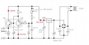
Т6 and т9 are the same output transistors as Т8 Т12What are T6 and T9 for? Bias control?
-Chris
Bias Control is performed by an independent voltage "Battery" source at 2.2 ... 2.6 V
Last edited:
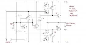
Can anyone be interested in a more advanced scheme than a "Diamond buffer"
This is may scheme of the "12 apostles" (attachment):
Hi Hennady,
Interesting, but aren't you at the mercy of outstanding matching requirements of PNP/NPN transistor specifications and stable, low noise power supplies to get a decent signal quality through this buffer? Unless of course this is just the broad principle and/or it is intended to make it as a monolithic IC? I seem to remember a similar circuit topology being employed in a commercial opamp, but I simply can't recall which one.
And a battery can of course be low noise, but it is not stable - what happens when it runs low? Or being recharged?
Sorry, I wasn't intending to be negative, but it would help me (and probably others) if you could please clarify.
Per
Hi.Hi Hennady,
And a battery can of course be low noise, but it is not stable - what happens when it runs low? Or being recharged?
It's simple - it's an electronic battery
see Attachment
Attachments
Last edited:
Hi.
It's simple - it's an electronic battery
see Attachment
Hi Hennady,
That is a lot of hardware to do the job.
And I don't understand the "50" (ohms?) at the "electronic battery".
129mA through 50 ohms would give over 6V drop, ie. more than the 7805 provides? Sorry, I try, but still don't get it.
Hi again memofer,
Just catching up on how you're getting along with the mods.
Your experience above of "a completely different amp" has been echoed by every single one of the Rotel owners I now have done the mods for.
If you feel adventurous and willing to report back on the thread on your results, I now have a spare set of prototype current mirrors and VAS transistor replacement pcb's for you to try out for free. I will of course provide detailed instructions on how to mount them in your amp.
Your call.
Hi AngelP,
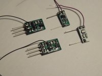
Well, It's been over 2 weeks since I installed the prototype boards you sent me and wanted to thank you again for your kindness!
I just wanted to report that my rotel is still kicking a$$! and that I have not had a single problem ever since whatsoever! Though, I don't listen to it very loud at all, just sometimes.
Installing the boards was very straight forward, thanks to your instructions, though, I have to tell you I was a little, or should I say very
nervous about installing these boards, because I sure was afraid to burn my amp, as it was the first time I did something this advanced to an amp, not to mention, it was the first time I dealt with Current mirrors and VAS, now I am so freaking glad I did! becuase the reward is really great.
At anyrate, here is a picture of the boards on the left channel, it was just a matter of removing 6 parts per channel then adding the boards, which it was fairly easy. After installing them, I was very surprised and relieved that the amp turned on and worked with out any issues at all, I mean, i didn't even had to adjust bias nor DC offset again!, it was great, they worked real good immediately. Sir, very well done on those boards.
Cheer!
Joaquin
Attachments
Last edited:
Thank you for your kind words Joaquin and good on you!
I am very pleased that even though the two modules were originally designed for the RA-8/900 series of Rotels, you actually succeeded in upgrading your RX-750 with them. I can guarantee that its THD/IMD etc. will have dropped like a stone. Enjoy!
People have asked me whether I would consider selling the VAS and CM modules - and why not?
I am not in this for any personal profit, the direct price of PCB, components, SMT pick and place manufacture, testing and packaging is about US$10 per module. So, it is $40 for the two pairs required. Postage comes on top of that.
They will of course come with detailed installation instructions, but some basic PCB soldering experience is still required.
I don't know how to get them on the diyAudio marketplace, maybe someone in here can help? Or maybe I can just put them on eBay?
Speaking of which, if you rather fancy me supplying the heavenly music box, I will soon have four cosmetically perfect and upgraded RA-931's ready for sale on eBay, just search "RA-931 AngelP Signature".
I also offer to do the full 42 component upgrade for Rotel owners who would prefer me to do the total rejuvenation/upgrade of their own beloved amp. I live in the UK, so please note that international shipping costs may be an issue.
Anyway, even though my good wife solidly subscribes to Chris' wife's motto: "Just because you can, doesn't mean you should" - she has generously allowed me an exemption in this case.
I know - I am a very lucky man!

I have been asked the following:
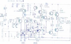
I enclose (somewhat) better pics of the modules and a schematic of the 6th RA-820AX mod where these new modules are employed.
T1 is connected as an “emitter follower” (EF) so the collector is not the output. The collector should just be at a stable dc voltage high enough and able to deliver the current through it and the emitter resistor which then “follows” the base input. (Think of it as like putting a unity gain buffer opamp in).
You can connect the T1 collector to V+ if you want, T1 is the SMD version of 2SC1845 so it can easily take the resulting 80V across it, but that doesn't give any improvement and there is no need to go beyond the 40V GND to V-. (BTW; If you connect the collector to the emitter of T3, the entire VAS 3 module will appear as one single diode protected darlington transistor with a hFE of about 2500.)
Firstly, the 2nd EF (T3) basically does the same thing as T1, only here it greatly reduces the load on the VAS (T2) caused by the following driver stage. This increases linearity by protecting the VAS transistor to do its job.
Secondly, the SOT23 version of the SC1845 and SA992 has a max. collector dissipation of 300mW. The bias stage current of 6mA with 40V across a single T2 would give 240mW – that may be ok, but it would still run uncomfortably hot.
Sharing the 6mA (2:4) between T2 and T3 solves the problem, and the module has been designed so the dominating 160mW heat from the T3 collector is readily dissipated down into the main PCB copper tracks as heat sink.
It works a treat, I have never measured temperatures over 48°C anywhere on the VAS3 module even under full load. And as you may infer from the version number, I have indeed been through a couple of VAS iterations before finally settling on this one.
Designing the module as a simple direct drop-in replacement for a traditional TO-264 or TO-220 NPN VAS transistor gives the option to easily upgrade other amps than the Rotels they were originally designed for, although there will obviously be some limitations.
Note that memofer's amp is a RX-950AX receiver with a very different PCB layout, yet he still made a success out of it.
I have just been asked whether I could improve a NAD 3030, which seems quite feasible.
Cheers,
Per[/FONT]
So i've been meaning to ask you a couple of questions about the VAS board, that I am not to clear on why you did that board with 3 transistors.
I am just trying to understand, learn so I can play with my own mods for my other receivers.
That would be the absolutely best reason to ask questions and there could be others that sit with the same or similar queries. I will try to answer as best I can, and maybe the sharp audio brains here on diyAudio will chip in with their expertise?I am just trying to understand, learn so I can play with my own mods for my other receivers.
I enclose (somewhat) better pics of the modules and a schematic of the 6th RA-820AX mod where these new modules are employed.
1. why the collector of the 1st transistor is connected to ground, not clear on why the output is being shorted to ground? will this cause a problem eventually?
The “VAS 3” module is a "EF-VAS-EF" stage, i.e. the middle VAS transistor is “sandwiched” between the two EF's. The 1st transistor (T1) performs like a buffer, reducing the current load on the input stage by its hFE, in this case by a factor of 350. This has been shown to greatly reduce the THD of the stage. Please cf. my measurements and cabirio's simulations (e.g. post 183)T1 is connected as an “emitter follower” (EF) so the collector is not the output. The collector should just be at a stable dc voltage high enough and able to deliver the current through it and the emitter resistor which then “follows” the base input. (Think of it as like putting a unity gain buffer opamp in).
You can connect the T1 collector to V+ if you want, T1 is the SMD version of 2SC1845 so it can easily take the resulting 80V across it, but that doesn't give any improvement and there is no need to go beyond the 40V GND to V-. (BTW; If you connect the collector to the emitter of T3, the entire VAS 3 module will appear as one single diode protected darlington transistor with a hFE of about 2500.)
2. why did you change the board to use 3 transistors? I thought your mod 5 used only 2 trainnies (EF-VAS) as you posted on your main thread.
[FONT=FreeSans, sans-serif]The reason for that is twofold: Firstly, the 2nd EF (T3) basically does the same thing as T1, only here it greatly reduces the load on the VAS (T2) caused by the following driver stage. This increases linearity by protecting the VAS transistor to do its job.
Secondly, the SOT23 version of the SC1845 and SA992 has a max. collector dissipation of 300mW. The bias stage current of 6mA with 40V across a single T2 would give 240mW – that may be ok, but it would still run uncomfortably hot.
Sharing the 6mA (2:4) between T2 and T3 solves the problem, and the module has been designed so the dominating 160mW heat from the T3 collector is readily dissipated down into the main PCB copper tracks as heat sink.
It works a treat, I have never measured temperatures over 48°C anywhere on the VAS3 module even under full load. And as you may infer from the version number, I have indeed been through a couple of VAS iterations before finally settling on this one.
Designing the module as a simple direct drop-in replacement for a traditional TO-264 or TO-220 NPN VAS transistor gives the option to easily upgrade other amps than the Rotels they were originally designed for, although there will obviously be some limitations.
Note that memofer's amp is a RX-950AX receiver with a very different PCB layout, yet he still made a success out of it.
I have just been asked whether I could improve a NAD 3030, which seems quite feasible.
Cheers,
Per[/FONT]
Attachments
This is great man!
Thanks for your white paper on your VAS3 Module, and nice to see your mod 6 schematic.
I am still ecstatic, to hear the difference when THD is lowered as much as you did.
If you ever happen to be in my town for any reason, let me know and I'll take you a beer or two or three or etc..

Thanks for your white paper on your VAS3 Module, and nice to see your mod 6 schematic.
I am still ecstatic, to hear the difference when THD is lowered as much as you did.
If you ever happen to be in my town for any reason, let me know and I'll take you a beer or two or three or etc..
Vbe multiplier bypass capacitor quandaries
I have been staring at the non-populated Vbe multiplier bypass capacitor position on the Rotel PCB. (Yes ok, some people may say that I have strange ways to pass time).
But it made me wonder – why was it apparently first designed in and then abandoned?
Then I started roaming the web for info, as I thought that there must surely be a simple way of calculating the optimal value for this device - or even some solid explanation of what it really does – or just a recommendation of a “best” starting value from experience?
I found nothing. Can anyone help?
The commercially implemented solutions I could find ranged from 10nF to 100uF! Does this indicate that the science behind it is anything but “settled”?
Self claims that it helps speed up the on/off switching of the drivers, others claim that it reduces the Vbe multiplier's impedance at high frequencies, some says there is a sonic difference and the LM391 datasheet claims it reduces distortion at high frequencies. Hmmm.
So I did what I always do – I tried it out on a real amplifier, listened and measured.
I had the following components at hand: 100nF ceramic, 1uF PP film, 22uF and 470uF e-lytics which I could freely plug in - or out of the circuit.
1) Sonic: To my ears (through speakers and headphones) there were no audible changes anywhere between 10nF and 470uF Vbe bypass and “no cap”.
2) Slew Rate: I tried to apply a 100kHz square wave and measure the SR. No change whatever cap that I put in.
3) Upper frequency -3dB limit: The amp on my desk ran smoothly to 180kHz (0dB/-3dB) regardless of the Vbe capacitor value.
4) Distortion: My soundcard test setup limits the measurable range to 22kHz, so I tried measuring THD using 5 and 10kHz fundamentals. Very little changes with different capacitors – if any.
5) Stability: The “no cap” amp is stable at any volume level with 8ohm//2uF test loads, adding caps around the Vbe circuit did not change anything.
So, what good is a Vbe bypass capacitor for
And was Rotel right in leaving it out in the final design?
- Home
- Amplifiers
- Solid State
- Improve a Rotel amp THD by 20dB!