tan(delta) is typically around 0.02, MKT has a tan(delta) of the same order of magnitude, polystyrene and polypropylene have a tan(delta) <0.001.
Class II ceramics and MKT also age. For class II ceramics, the specified value applies 1000 hours after the last time they got heated above the Curie temperature (as often happens during soldering) and the value drops with the logarithm of time, typically something between 2 % and 8 % per factor of ten increase of time.
Class II ceramics and MKT also age. For class II ceramics, the specified value applies 1000 hours after the last time they got heated above the Curie temperature (as often happens during soldering) and the value drops with the logarithm of time, typically something between 2 % and 8 % per factor of ten increase of time.
In between the DAC output pin (pin6 & 8) we have the BC807 base-emitter junction and a small valued (under 2ohm) emitter degeneration resistor. (The DCR of the inductors is well under 1ohm so I'm neglecting them.) The former can be assumed to be 0.65V and the resistor voltage drop will be at most 5% of this value. So let's go for 0.69V as the difference between BREF and the DAC's output. It means we need 1.5V+0.69V = 2.19V below the positive supply for BREF. At 5V this means 2.81V.
Awesome, thank you!
What happens if the emitter voltage is too high? Too low?
Also, what made you choose an LED for setting the BREF voltage (as opposed to the TL431)?
Sounds close enough, looks like your math was pretty good")
Woohoo! I'll allow myself a small celebration of progress in learning.
If the emitter voltage is too high there's the distinct possibility that the DAC won't be able to source current into the I/V transistor, leading to distortion. Depends on the particular DAC how much beyond 3.5V it can take.
OTOH is the emitter voltage is too low then there's the chance of running into clipping at the collector due to premature saturation. This is less of a problem when the max output voltage level is reduced - such as in the case where you're content with just 7VRMS out of your 26dB gain amp.
As for not choosing a TL431 - simple reason for that. TL431 is only good for voltages of 2.5V and higher, and I want about 2.1 to 2.2V. There is a TLV431 for lower voltages but its not a part I'm familiar with. Maybe I should acquaint myself with it
When you make a sigma-delta DAC with zero-order hold, the sin(pi f/fs)/(pi f/fs)-shaped roll-off of its zero-order hold is negligible because fs is very large.
That does not necessarily mean that the response of the DAC is flat. Sigma-delta modulators have a signal transfer function that can peak, droop or stay perfectly flat depending on how they are designed, the interpolation chain can have ripples, peak or droop and you need an analogue reconstruction filter that is not perfectly flat.
I would expect that they are generally designed to have a response that is close to being flat with everything included: interpolation chain, sigma-delta modulator, DAC, integrated reconstruction filter (if any) and the recommended output application circuit, but that's just an educated guess.
Hi Abraxalito,
I am very interested in your treble correction filter. I am new to NOS and I have to ask:
In my mind, an important (theoretical) strength of NOS is its ability to accurately render the original signal's transients. With the few Sigma Delta components I have owned, I have never achieved a sound I found convincingly real...neither fast nor slow digital roll-off filters sound natural to my ears. Perhaps I am wrong, but I have come to blame this on the pre and/or post- ringing induced by the filters, which can be easily seen on a square wave produced by the DAC.
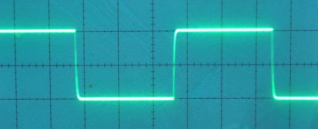
Here's a pretty bad example showing results from an oversampling PCM1794:

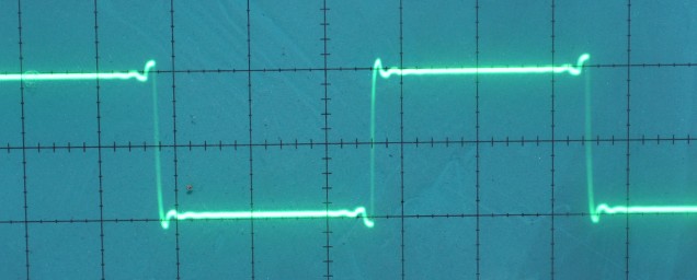
In contrast, a NOS DAC can produce a perfectly shaped square wave without the aberrations. Measurements from the same DIYA member of a NOS TDA1541:

My question is, what happens when we correct the NOS treble droop (inherent at 44.1kHz sampling rates) using the electronic LC filter you have designed? Do we get those same little oscillations? It looks like the TOTALDAC engineers tried an approach similar to yours and went from this:
to this:
I'm not saying the treble correction isn't worth it. The TOTALDAC guys seem to think they hit the sweet spot with the compromise: "When the FIR filter is activated some oscillations are visible but the amplitude and the number of oscillations is much smaller than those on conventional DACs. This is part of what explains the natural sound of the DAC."
Sheesh, now that I think about it, nearly all of our music has already been through multiple EQ filters in the studio that introduce ringing and phase shift. Maybe the NOS advantage is more complex than this one simple feature we can see through an oscilloscope... Your thoughts? Have you put a scope on your filtered DAC output before?
I am very interested in your treble correction filter. I am new to NOS and I have to ask:
In my mind, an important (theoretical) strength of NOS is its ability to accurately render the original signal's transients. With the few Sigma Delta components I have owned, I have never achieved a sound I found convincingly real...neither fast nor slow digital roll-off filters sound natural to my ears. Perhaps I am wrong, but I have come to blame this on the pre and/or post- ringing induced by the filters, which can be easily seen on a square wave produced by the DAC.
Here's a pretty bad example showing results from an oversampling PCM1794:
In contrast, a NOS DAC can produce a perfectly shaped square wave without the aberrations. Measurements from the same DIYA member of a NOS TDA1541:
My question is, what happens when we correct the NOS treble droop (inherent at 44.1kHz sampling rates) using the electronic LC filter you have designed? Do we get those same little oscillations? It looks like the TOTALDAC engineers tried an approach similar to yours and went from this:
to this:
I'm not saying the treble correction isn't worth it. The TOTALDAC guys seem to think they hit the sweet spot with the compromise: "When the FIR filter is activated some oscillations are visible but the amplitude and the number of oscillations is much smaller than those on conventional DACs. This is part of what explains the natural sound of the DAC."
Sheesh, now that I think about it, nearly all of our music has already been through multiple EQ filters in the studio that introduce ringing and phase shift. Maybe the NOS advantage is more complex than this one simple feature we can see through an oscilloscope... Your thoughts? Have you put a scope on your filtered DAC output before?
Last edited:
Hi Abraxalito
Hi se, thanks for your interest and questions. Also I'm enjoying the thread on HeadFi that you're contributing to.
In my mind, an important (theoretical) strength of NOS is its ability to accurately render the original signal's transients. With the few Sigma Delta components I have owned, I have never achieved a sound I found convincingly real...neither fast nor slow digital roll-off filters sound natural to my ears. Perhaps I am wrong, but I have come to blame this on the pre and/or post- ringing induced by the filters, which can be easily seen on a square wave produced by the DAC.
I agree that subjective performance is paramount with any DAC, I'm not yet convinced though that the digital filter's performance is what holds back Sigma-Delta type DACs. I've come to this conclusion simply because introducing upsampling on my NOS TDA1387 can improve the SQ - I've noticed on some set-ups I get more 'air' and/or 'bloom'. Upsampling always needs some kind of digital filtering to be introduced.
The squarewave response you've shown for PCM1794 is typical for a linear phase reconstruction filter.
In contrast, a NOS DAC can produce a perfectly shaped square wave without the aberrations.
Yeah it can produce a 'perfect' square wave but only on the bench when fed with a sequence of samples which can't arise from a real recording. So these perfect looking scope shots are only of academic interest, any recording you buy will have already gone through an anti-aliasing filter at the ADC. That AAF will contribute at least post-ringing and most likely pre-ringing too as ADCs nowadays normally contain linear phase digital filters.
My question is, what happens when we correct the NOS treble droop (inherent at 44.1kHz sampling rates) using the electronic LC filter you have designed? Do we get those same little oscillations?
Yes, we do though only after the sharp edge, not before it. In other words, my analog filter contributes only post-ringing, no pre-ringing.
The TotalDAC response looks like a very short FIR filter, you'll pay for this in the frequency response being rather shallow.
I'll get around to your later questions in another post, lunch time is beckoning me
Here's the revised *4 DAC schematic as there are component errors in that I put up in post #20. C11 & C12 should be 2.2uF, not 1uF.
Back to the earlier question about oscillations - a filter only rings when its excited and to excite it it needs energy in the input signal close to its resonant frequency. There's not much in audio above 16kHz or so so I reckon the emphasis on ringing is overblown. Your final point se is a good one - there's the upstream AAF to be accounted for at the very least, plus ringing from any EQs that have been employed.
I have put a scope on the output of one of my prototype DACs when playing a sinewave @ 15kHz or so. The usual NOS 'stairsteps' aren't anywhere to be seen but there is a visible modulation of the 15kHz by its first image frequency. I think I posted up a picture before in another thread where this was being discussed.
Attachments
There are at least six hypotheses to explain why non-oversampling DACs with hardly any reconstruction filter sound better to some than oversampling DACs:
1. Ultrasonic pre- and postringing of interpolation and reconstruction filters messing up the sound:
requires one to assume that ultrasonics can be audible
2. Ultrasonic spectral copies in the output signal of a NOS DAC without reconstruction filter improving the sound:
requires one to assume that ultrasonics can be audible
3. Pre-echo of linear phase filters with too large passband ripple messing up the sound:
This pre-echo occurs in the frequency range that is traditionally considered audible. The effect should depend on the size and number of the passband ripples: the smaller the ripples, the smaller the pre-echo and the fewer the ripples, the smaller the time distance between echo and main signal and the better the masking.
4. Slight sin(x)/x treble roll-off improving the sound of NOS DACs without reconstruction filter:
similar "improvement" should be obtainable with a smooth low-pass after a DAC with reconstruction filter (with or without oversampling)
5. Intersample overshoots on peak-sample-normalized recordings causing clipping in digital interpolation chains with no headroom:
attenuating the recording before any interpolation or sample rate conversion takes place should solve the issue
6. Expectation bias
No idea which one or which ones are the correct explanation.

I have put a scope on the output of one of my prototype DACs when playing a sinewave @ 15kHz or so. The usual NOS 'stairsteps' aren't anywhere to be seen but there is a visible modulation of the 15kHz by its first image frequency. I think I posted up a picture before in another thread where this was being discussed.
Did some searching. Is this your pic you were referring to? 16kHz. Why are there no stairsteps?
The short answer is - the stairsteps got left behind in the filter. That's its purpose, getting rid of high frequency components - that is elements of the waveform above the Nyquist frequency (22.05kHz). The modulation visible is because here the above-Nyquist frequency (it'll be about 28kHz) is imperfectly filtered. Meaning only attenuated, not totally eliminated.
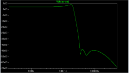
Here's the frequency response plot of the filter used. 28kHz gets about 26dB attenuation so the image frequency is about 1/20th of the fundamental.

Here's the frequency response plot of the filter used. 28kHz gets about 26dB attenuation so the image frequency is about 1/20th of the fundamental.
Last edited:
Hi,
Can you post up your ltspice?, I want to have a play with 5V and resistors for two chips.
Why do you run 4 or even 8 chips, direct headphone out? For line-out I find two chips is plenty!
Also regarding your circuit am I correct in saying it is subduing the lower frequency rather than amplifying the frequencies post roll-off?
Cheers,
Andrew
Also, Abraxalito, I appreciate your explanation but I can't seem to open the last image you attached. It just says loading...forever. Thanks for trying--I am a visual learner to the max (I have a degree in art, not EE!), hence my affinity for FFTs, frequency response charts, and scope shots). I also use use my ears to judge too, BTW
I was under the impression that NOS dacs output a stairstep wave at any frequency. Is this a total myth?
I was under the impression that NOS dacs output a stairstep wave at any frequency. Is this a total myth?
Can you post up your ltspice?, I want to have a play with 5V and resistors for two chips.
I've not LTspiced the DAC chips themselves, only the output filter and I/V stage. The file for that I posted in response to Patrick's request earlier in the thread.
Two chips is plenty with an output buffer, otherwise the output impedance is a bit higher than I'm comfortable with. For example with 2mA total current (from two chips @ 5V) then to get the usual 2VRMS needs an I/V resistor about 3k. I go for 1VRMS, with 4 chips I get below 1k for the output resistance. There's no direct headphone out until you get to 16 or so chips, not enough current for decent levels with fewer.Why do you run 4 or even 8 chips, direct headphone out? For line-out I find two chips is plenty!
When I'm using an output buffer, I'll use a single chip, or perhaps two in anti-phase. Definitely no need then for additional chips.
Sorry, I cannot understand your question. The filter is having no effect on the lower frequencies, its a low pass.Also regarding your circuit am I correct in saying it is subduing the lower frequency rather than amplifying the frequencies post roll-off?
@se - I'm trying a different method of posting the filter's response.
Attachments
X-DA2 - ES9023
Made by the same manufacturer as the TDA5102 I reviewed earlier, as is obvious by how much commonality there is between it and the X-DA3 on the PCB layout. Both use output capacitors (which I've removed).
So, there is a clear winner, and it's NOT the TDA5102.
There is no comparison, the ES9023 offers a level of ambience, sound-stage and punch that the TDA5102 can't compete with. The level of detail in the mid-range, what it can do for hi-hat cymbals and intricate detail is something else.
It really is truly excellent and has me wondering of the ES9018 can actually better it, or if in fact anything can.
snoopy33, are you talking about this SA9023 ES9023 board?
https://ae01.alicdn.com/kf/HTB1oGbPQVXXXXX0XVXXq6xXFXXXV/220353547/HTB1oGbPQVXXXXX0XVXXq6xXFXXXV.jpg
https://ae01.alicdn.com/kf/HTB1oGbPQVXXXXX0XVXXq6xXFXXXV/220353547/HTB1oGbPQVXXXXX0XVXXq6xXFXXXV.jpg
snoopy33, are you talking about this SA9023 ES9023 board?
https://ae01.alicdn.com/kf/HTB1oGbPQVXXXXX0XVXXq6xXFXXXV/220353547/HTB1oGbPQVXXXXX0XVXXq6xXFXXXV.jpg
Think it's this one
X-DA2 SA9027+ES9023 24BIT/96KHZ Asynchronous USB DAC/HIFI Sound Card Decoder Board - best store-online
- Status
- This old topic is closed. If you want to reopen this topic, contact a moderator using the "Report Post" button.
- Home
- Source & Line
- Digital Line Level
- Impressions: USB DAC: TDA1387 NOS vs PCM5102A Delta-Sigma