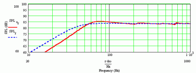
Jmmlc said:Svante said:
<... driving the cone with a constant force/current will result in a resonance peak...>
Hello
While I agree with ou on most of what you wrote, I refuse the generalization you do in the quoted sentence.
Ok, I just had a quick look at the document. I have a two comments.
First, the use of an impedance equalization network will counteract the effects of current drive. In this way, the peak that I mention will be lower or even cancelled.
Second, if one starts off with a system that has a far too sloping low-frequency response, like a driver with a very low Qts or an open baffle, a bit of peakedness might be good. I think that is what you see in many of the graphs comparing U and I drive.
The case I talked about was a typical closed box system. Indeed such a system will have a peak at the resonance in the typical case. Of course the skilled loudspeaker designer can find means to counteract this, or make use of it.
Hello, Svante,
If you read carefully Nelson Pass's document you'll see that equalization (using L and C) of the "resonance" related to the impedance peak is not always needed.
Nelson's give the value of the parallel resistor used for current drive, this is equal to the value of the series resistor that you may used with constant voltage drive to ensure proper damping of the resonance. Generally the resistor value appears to be 47ohms.
Someone could argue that this is no more a current drive. In fact we have to compare it to the max impedance (at resonance peak) of the loudspeaker (loaded). Generally with low Qts loudspeakers this max value is quite low (rarely above 30 ohms) .
So the current drive will be effective for most of the frequency range and the R value will optimize the response around the resonance.
Best regards from Paris,
Jean-Michel Le Cléac'h
Jmmlc said:
Nelson's give the value of the parallel resistor used for current drive, this is equal to the value of the series resistor that you may used with constant voltage drive to ensure proper damping of the resonance. Generally the resistor value appears to be 47ohms.
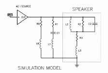
Okay, I have some questions about Nelson Pass' illustration, which appears on page 5 of his paper, and which I reproduce below.
Number one, is the AC source in the drawing one of infinite impedance?
Number two, Nelson Pass made some reference to R0 being somewhat equivalent to the series resistor Rs in the closed box voltage driven model. In that voltage driven model, the series resistor Rs serves to raise the Qtc of the driver/box combo. A parallel resistor, however, will not lower it in a voltage driven situation.
This R0 resistor-does it serve to lower the Qtc of the driver/box combo? Is that how it works in a current drive situation?
And what does it lower the impedance to-47 ohms? Or is the 47 ohms in parallel with the current source which has a finite impedance?
Number three. If that 47 ohm R0 was used with the Shabda amp, which has an output impedance of 63 ohms, would the total output impedance be 26.9 ohms?
Attachments
I don't have the answer to all the questions, but the source to the left should be a current source (it says "AC I SOURCE) and the ideal current source always has an infinitely high output impedance.
The series resonance can be set to cancel the resonance peak mof the driver, and the effect of that is to cancel the peak in the response that occurred in my previous examples. I am a bit more confused about the R0 L0 circuit; if it had been a series RC circuit it would have been a conjugate link, that would cancel the effect that the voice coil inductance has on the impedance (more or less). So if it had been an RC circuit, the whole impedance seen from the current source could have been almost resistive. This, in turn would have produced a nearly constant voltage across the driver, but driven from a non-zero output impedance. Quite interesting.
The series resonance can be set to cancel the resonance peak mof the driver, and the effect of that is to cancel the peak in the response that occurred in my previous examples. I am a bit more confused about the R0 L0 circuit; if it had been a series RC circuit it would have been a conjugate link, that would cancel the effect that the voice coil inductance has on the impedance (more or less). So if it had been an RC circuit, the whole impedance seen from the current source could have been almost resistive. This, in turn would have produced a nearly constant voltage across the driver, but driven from a non-zero output impedance. Quite interesting.
My understanding was R0 L0 as well as R1 C1 L1 are there to create a 'less ideal' current source; to reduce the overal gain going to the driver based solely on its rising impedance at resonance and high impedance. I.e. the power gain ends up being too high and you would see excessive peaking @ resonance, and there would be too much 'boost' @ high frequency to the point it sounds unnatural.
From what I recall when I read the article, those values were largely arrived at 'by ear'. Of course the RCL values are computed to coincide with the resonance peak, but the "Q" of the stage was determined through trial and error in listening test; same for the R0L0 combo. ...again, as I recall. I could be wrong.
From what I recall when I read the article, those values were largely arrived at 'by ear'. Of course the RCL values are computed to coincide with the resonance peak, but the "Q" of the stage was determined through trial and error in listening test; same for the R0L0 combo. ...again, as I recall. I could be wrong.
m8o said:My understanding was R0 L0 as well as R1 C1 L1 are there to create a 'less ideal' current source; to reduce the overal gain going to the driver based solely on its rising impedance at resonance and high impedance. I.e. the power gain ends up being too high and you would see excessive peaking @ resonance, and there would be too much 'boost' @ high frequency to the point it sounds unnatural.
From what I recall when I read the article, those values were largely arrived at 'by ear'. Of course the RCL values are computed to coincide with the resonance peak, but the "Q" of the stage was determined through trial and error in listening test; same for the R0L0 combo. ...again, as I recall. I could be wrong.
I think we are saying the same thing, but from different perspectives.
The values may of course be different from those I outlined, and for the skilled engineer they are degrees of freedom that can be used to acheive a desired frequency response, pretty much like an equalizer but with different knobs.
There is nothing magic about it, though.
I don't see how the R1, C1 and L1 can be set to cancel the bass resonance. For one thing, L1 is absent in most cases. In the case where there is an L1, the resonance is in the tweeter range.
In the Fostex 208ES, for example, on page 7 of the paper,
R1=3.9 ohms
C1=4.7 uF
L1=0.5mH
If you multiply those numbers out, they resonate at 3,280 Hz.
The fact that most of the drivers don't have any L1 would seem to indicate that we have an LC circuit designed to deal with high midrange and tweeter range problems.
Most drivers also don't have an L0. So we are left, with most drivers, with one parallel branch of 47 ohms in most cases, and an LC circuit dealing with problems nowhere near the bass.
If I am getting something wrong, please let me know.
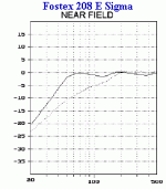
Now, if we take that R0, which is 47 ohms in most cases, and substitute it for Rs in the voltage drive model, we end up with a bass hump which we are not seeing on these charts.
That is why I am wondering if that AC current source has infinite impedance, or if it has a finite impedance that R0 would be in parallel with, thereby lowering the total output impedance and perhaps delivering a value which we can use for Rs in the voltage drive model to get curves such as these.
That is why I am wondering if that AC current source has infinite impedance, or if it has a finite impedance that R0 would be in parallel with, thereby lowering the total output impedance and perhaps delivering a value which we can use for Rs in the voltage drive model to get curves such as these.
Hi,
Post#67
No, I think your observations are quite right.
Post#68
This is not exactly what you should do. If RO is chosen to 47 Ohms and serves its purpose for a certain current amplifier and driver, thus the peaking effect at the low end for the speaker is lowered to an acceptable value that otherwise would exist without the paralleled resistor which is caused by the finite output amplifier impedance, constant current or not.
Then by applying Thevenin’s Theorem, using the paralleled 47 Ohm resistance and the amplifiers output resistance or corresponding 1/(constant current gain)= V/A = Ohm if the amplifier is of a constant current type together with summing all series resistance that might exist all the way to the binding posts of the driver you will end up with a Thevenin equivalent of a voltage source with an new extern series resistance that when used to drive the speaker returns exactly the same FR curve.
It has an finite impedance if the amplifier has (is considered to have) a low damping factor or an output impedance that would show up if connected to a speaker as a series loss together with a noticeable increase of the Qtc, this is the most common case, or for a perfect constant current source with infinite resistance the peaking would be severe both at the low end speaker box resonance and at high frequencies where the impedance is climbing without the paralleled R0.
b
Post#67
If I am getting something wrong, please let me know.
No, I think your observations are quite right.
Post#68
Now, if we take that R0, which is 47 ohms in most cases, and substitute it for Rs in the voltage drive model, we end up with a bass hump that we are not seeing on these charts.
This is not exactly what you should do. If RO is chosen to 47 Ohms and serves its purpose for a certain current amplifier and driver, thus the peaking effect at the low end for the speaker is lowered to an acceptable value that otherwise would exist without the paralleled resistor which is caused by the finite output amplifier impedance, constant current or not.
Then by applying Thevenin’s Theorem, using the paralleled 47 Ohm resistance and the amplifiers output resistance or corresponding 1/(constant current gain)= V/A = Ohm if the amplifier is of a constant current type together with summing all series resistance that might exist all the way to the binding posts of the driver you will end up with a Thevenin equivalent of a voltage source with an new extern series resistance that when used to drive the speaker returns exactly the same FR curve.
That is why I am wondering if that AC current source has infinite impedance, or if it has a finite impedance that R0 would be in parallel with, thereby lowering the total output impedance and perhaps delivering a value which we can use for Rs in the voltage drive model to get curves such as these.
It has an finite impedance if the amplifier has (is considered to have) a low damping factor or an output impedance that would show up if connected to a speaker as a series loss together with a noticeable increase of the Qtc, this is the most common case, or for a perfect constant current source with infinite resistance the peaking would be severe both at the low end speaker box resonance and at high frequencies where the impedance is climbing without the paralleled R0.
b
Sorry if I’ve confused you all here above.
A rephrasing of my first comment of post#68 follows:
EDIT:
This is not exactly what you should do.
If RO is chosen to 47 Ohms and serves its purpose for a certain current amplifier and driver, then the peaking effect at the low end for the speaker is lowered to an acceptable value that otherwise wouldn’t exist without the paralleled resistor.
The finite output amplifier impedance, constant current or not, causes the peaking effect.
b
kelticwizard said:I don't see how the R1, C1 and L1 can be set to cancel the bass resonance. For one thing, L1 is absent in most cases. In the case where there is an L1, the resonance is in the tweeter range.
In the Fostex 208ES, for example, on page 7 of the paper,
R1=3.9 ohms
C1=4.7 uF
L1=0.5mH
If you multiply those numbers out, they resonate at 3,280 Hz.
Ah, ok, I didn't look at the values at all, and I am not familiar with how this circuit is typically used.
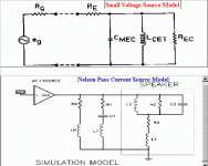
I've been trying to substitute the output voltage impedance of the current source for Rg-the source voltage-in the Small voltage model. The two models are shown below. It does not work exactly, but I have gotten some fairly interesting readings.
Attachments
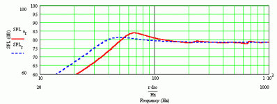
If we take that R0 impedance, 47 ohms, and plug it into Martin J King's software for the Fostex model, we get the following output. Note that the SPL is reduced-something which might not happen with the curent source model with the 47 ohms in parallel. Moreover, the shape of the bass curve does not resemble the current source.
Attachments
However, if we take that 47 ohms and cut it approximately in half to 23 ohms, and make that the Rg of the voltage model, we get a bass curve which roughly resembles the current source model, output R0 = 47 ohms. In the voltage drive model, the midrange SPL is reduced, however.
Attachments
Now, one question I would like to ask. In the votage model, if you give Rg a value like 10 ohms or higher, you get a reduction in midpoint SPL.
M question is, if your speaker is rated 97 dB @ 1M/1W, and you hook it up to a constant current source or a source with an output impedance of 47 ohms attainable without a resistor, will the midpoint SPL still be 97 dB at 1M/1W ?
Or will the SPL go down as if you took a voltage source, Rg < 0.1, and put a 47 ohms resistor in series with it?
Hello,
With a "voltage source" amplifier 1 watt is defined as 2,83volts on a 8ohms load
With a "current source" amplifier 1 watt is defined as 0,3535A in the 8ohms load.
RMS is defined with reference to the power dissipated on the (total) load at the output of the amplifier.
When we put a series resistor the (total) load is the loudspeaker + the series resistor. When using the amplifier without series resistor the load is reduced to the loudspeaker only.
The output impedance of the amplifier should not be considered as making part of the load.
As long as the "current source" amplifier doesn't clip when output peak voltage reaches supply voltage and is able to feed the demanded current through the load there will be no reduction in the RMS.
This means that, in order to avoid clipping, a current source amplifier or transconductance amplifier needs to be calculated taking in account the max impedance of the loudpeaker. So the supply voltage should generally be much more large than with a "voltage source" amplifier...
Best regards from Paris.
Jean-Michel Le Cléac'h
- Status
- This old topic is closed. If you want to reopen this topic, contact a moderator using the "Report Post" button.
- Home
- Loudspeakers
- Multi-Way
- Impedance and current-source amplification
