Hi all
In the following links there are some articles which I believe provide some information relevant to the topic under discussion:
http://sound.westhost.com/z-effects.htm
http://www.firstwatt.com/downloads/cs-amps-speakers.pdf
http://www.firstwatt.com/downloads/cs-xover-networks.pdf
My opinion is that the articles of "Audio Anthology" which I mentioned in post#33, provide indepth analysis and a "good old days" reasoning. The "Audio Anthology" Volumes can be ordered through this link:
http://www.audioxpress.com/bksprods/BKSGENHIS.htm
Regards
George
soongsc said:Svante, I'm there is another thread that talks about cable differences. I do think each different cable may have differences. For whatever technical reason, we probably should discuss it in that thread. But I think the impedance effects does influence the result even though it may seem very small. It's only a matter of how small until the effects are not audible.
Yes, I'm sure there are multiple threads on cables.
 And I am pretty convinced that characteristic impedance per se is not an important factor if only the amplifier is well behaved.
soongsc said:
Phase response as well as frequency response are equally important. We have been able to identify many good qualities associated with both.
Ok, so how do you know when you listen to one or the other? Have you done listening tests with only amplitude changes, but no phase differences and vice versa? Otherwise it is virtually impossible to tell which percept that corresponds to which physical properety.
I would recommend you to build an all-pass filter and compare the sound when you connect or bypass it. Be careful to match the levels properly, and verify that the frequency response is flat for the allpass filter.
An externally hosted image should be here but it was not working when we last tested it.
soongsc said:
I am also quite interested in how driver back EMF effects current source versus voltage source amplifiers.
You can see that in the graphs I posted previously. The effect is that the response near the driver resonance is increased.
An externally hosted image should be here but it was not working when we last tested it.
Maybe you'd like to post some opinions about speaker cables here.
http://www.diyaudio.com/forums/showthread.php?postid=840473#post840473
True, it is difficult to attribute listening differences to phase alone because almost every change you make may change other responses. I am not prepared to spend time just to prove a point though, all I can say is we just need to follow sound engineering practices. However, I do notice certain transient sonic characteristics that I associate with phase, and once resolved, the specific sonic characteristics disappear.
Back EMF occurs not only at the resonance frequency of the driver, but any time the driver is driven back to neutral position by the suspension system.
gpapag said:Hi all
In the following links there are some articles which I believe provide some information relevant to the topic under discussion:
http://sound.westhost.com/z-effects.htm
http://www.firstwatt.com/downloads/cs-amps-speakers.pdf
http://www.firstwatt.com/downloads/cs-xover-networks.pdf
My opinion is that the articles of "Audio Anthology" which I mentioned in post#33, provide indepth analysis and a "good old days" reasoning. The "Audio Anthology" Volumes can be ordered through this link:
http://www.audioxpress.com/bksprods/BKSGENHIS.htm
Regards
George
Those ariticles from Nelson Pass were informative indeed.
I wish there were a cheaper way to get all volumes. But I don't see volume 2 there?
Hi soongst
I didn't notice this. You are right.
It seems that it is sold out.
E-mail them, there is a chance to re- print it.
Or have a look at online bookstores (amazon ect).
Regards
George
But I don't see volume 2 there?
I didn't notice this. You are right.
It seems that it is sold out.
E-mail them, there is a chance to re- print it.
Or have a look at online bookstores (amazon ect).
Regards
George
Hello,
As I could'nt read the forum during the 2 last weeks I come back on that interesting discussion.
In the message
http://www.diyaudio.com/forums/showthread.php?postid=1077309#post1077309
Svante said:
"This is because most speakers are designed for a 0 ohm driving impedance."
In fact this is only true for enclosures. The different models used to design bass-reflex and closed enclosures are based on the hypothesis of a voltage source.
Now, if we considered the voice-coil loudspeaker itself we cannot say that it is optimized or designed considering a voltage control. Even in a voice-coil loudspeaker the current through the coil matters and not the voltage across. Remember the formula giving the force versus current ( + flux and length of wire in the flux):
F = B . L . i
Now it has been said that the frequency response is modified according to the variation in the impedance curve. That's one way to look at it but another can be used.
By example in the graph given by Svante in message:
http://www.diyaudio.com/forums/showthread.php?postid=1079118#post1079118
we can see that driving the voice-coil loudspeaker in current in the frequency interval for which the impedance is almost purely selfic lead to a zero degre phase and a perfectly linear response (this will be the case by example with compression driver, give a look to the measurement I did on a TAD TD2001 with :
- 1) a very low output impedance amplifier,
- 2) the same with an additional 16ohms series resistor
and
- 3) my Shabda amplifer which one possess a 53ohms output impedance).
http://www.musique-concrete.com/mesures/321gain.gif
The increased linearity obtained using the high impedance amplifier is obvious.
Now there is the low frequency register that means around the resonance. In the old days amplifiers use to have a potentiometer acting on damping (in fact acting on output impedance).
Many people fear that using a high output impedance results in poor damping of their bass loudspeaker (or they fera about back EFM). In fact more often than thought a better impulse response can be obtained using some output impedance (after optimization ) and also a more linear response until the low frequency cut-off.
This leads to the question of the design of enclosures and crrossover when a medium or large output impedance amplifier is used. Hawksford and Pass wrote interesting things about that subject.
Best regards from Paris,
Jean-Michel Le Cléac'h
Been looking online for some schematics of a one or two watt constant current amp that is not a voltage amp with a big resistor hooked up the output, but rather a genuine constant current amp.
Are these things also called current sources? I always assumed a current source was part of some amp's power supply, (my knowledge of amps is limited, but not quite completely nonexistent).
How about a current mirror, is that the same thing? I've seen op-amp manuals which speak of configuring an opamp for use as a current mirror, whatever that is.
Hello,
The name "current source" can me somewhat misleading as confusion can arise with a "constant current source" which is a different thing.
We can consider a current ampliifer as a "controlled current source".
A current source amplifier takes the signal as voltage at the input and converts it as current at its output. That output current is proportionnal to the input voltage. So we can call those amplifers "transconductance amplifiers" .
BTW there is no need of a series resistor at the output of such transconductance amplifier to obtain a large output impedance. The large output impedance is generally due to the internal impedance of the power transistor - or of the power tube- itself. Current feedback may also lead to a rise of the output impedance.
http://en.wikipedia.org/wiki/Transconductance
On the DIY forum an interesting discussion exists on such amplifiers:
http://www.diyaudio.com/forums/showthread.php?s=&postid=1106547#post1106547
You can found intersting informations about current amplifer on Nelson Pass website at:
http://www.passdiy.com/articles.htm
and specially his paper:
http://www.passdiy.com/pdf/cs-amps-speakers.pdf
Nelson Passs designed many current amplifers see:
http://en.wikipedia.org/wiki/Pass_Labs
one of those being his "First Watt".
A current mirror is another "animal" used to copy a current through a given stage of a preamplifier or an amplifier to anpother stage.
http://en.wikipedia.org/wiki/Current_mirror
Best regards from Paris
Jean-Michel Le Cléac'h
kelticwizard said:Been looking online for some schematics of a one or two watt constant current amp that is not a voltage amp with a big resistor hooked up the output, but rather a genuine constant current amp.
I posted this on the first page of this thread. The series resistor is SMALL, typically 0.1 ohms, yet the circuit produces an output current that in largely independent of the load impedance.
http://www.diyaudio.com/forums/showthread.php?postid=1071768#post1071768
Jmmlc said:Svante said:
"This is because most speakers are designed for a 0 ohm driving impedance."
In fact this is only true for enclosures. The different models used to design bass-reflex and closed enclosures are based on the hypothesis of a voltage source.
Now, if we considered the voice-coil loudspeaker itself we cannot say that it is optimized or designed considering a voltage control. Even in a voice-coil loudspeaker the current through the coil matters and not the voltage across. Remember the formula giving the force versus current ( + flux and length of wire in the flux):
F = B . L . i
Having a 0 ohm driving impedance is exactly the same thing as having a constant voltage source.
And yes, most loudspeaker systems are designed for constant voltage drive.
Any series impedance will affect the frequency response and of course it is possible to take these effects into account when a system is designed, but IMO this is rare. Very rare.
It is true that the force acting on the cone is proportional to the current, and the immediate thought might be that this means that current drive is the best. However, it is not only the force acting on the cone that determines the velocity or acceleration it gets. The mechanical impedance also does. At resonance, the cone is particularly easy to move, and consequently, driving the cone with a constant force/current will result in a resonance peak. Driving it with a constant voltage source will reduce the current at resonance due to the increased electrical impedance there, and this balances the peak away, more or less.
Svante said:
I posted this on the first page of this thread. The series resistor is SMALL, typically 0.1 ohms, yet the circuit produces an output current that in largely independent of the load impedance.
http://www.diyaudio.com/forums/showthread.php?postid=1071768#post1071768
Yes, you did. And you called my attention to it once before also. The problem I have with the schematic is that I'm not sure what I am seeing.
I realize the big triangle is an IC amp. However, those two little triangles labelled Iout-are those components?
I was wondering if the small triangles were just illustrations for Current Out, or if they were the components for the current source or current mirror maybe something else. Diodes, maybe?
That is why I started looking elsewhere.
kelticwizard said:
Yes, you did. And you called my attention to it once before also. The problem I have with the schematic is that I'm not sure what I am seeing.
Ah, well, my memory isn't the best...
kelticwizard said:
I realize the big triangle is an IC amp. However, those two little triangles labelled Iout-are those components?
I was wondering if the small triangles were just illustrations for Current Out, or if they were the components for the current source or current mirror maybe something else. Diodes, maybe?
That is why I started looking elsewhere.
Those are just arrows indicating that there is a current flowing through the wire. The circuit is really simple, just a power OP, a resistor and the speaker. The power supply is not drawn, you will have to add that.
hehe... Oooo, nice thread. This very thing has been my obsession the last few weeks. I wish I'd seen this thread sooner.Svante said:You can make a very-near ideal current source. It will of course have the same limitations regarding maximum output voltage and current as the typical near-ideal voltage source (=most normal amplifiers).
Here is a proof-of-concept design:
An externally hosted image should be here but it was not working when we last tested it.
Yes, I'm using that technique; with some notable differences. I'm in the design phase of building 3 stereo glainclone amps [using LM4780] to tri-amp my 3 horns in my Klipsch La Scalas. With this sort of circuit, you want to avoid impedance variations brought on by passive x-over that will "falsely" affect the voltage and thus power delivery, so I'll be using an active crossover too (sort of implied in tri-amping anyway). I'm just using a 1 ohm floating ground as opposed to 0.1 ohm. ...actually, there are a lot more differences in the manner the feedback is structured, but I won't get bogged down with that. I am of course, not looking to build a 'perfect' constant current source but rather a good sounding one.

Also, Based on Nelson Pass's work, I learned you don't actually want "pure-constant-current"; the voltage differential between the voltage your amp will be expected to deliver when the speaker is at high impedance (@ high freq and resonance) compared to when it's at low impedance, takes the amp far out of its safe operating area. Additionally, if the amp could even deliver the voltage, it would end up providing too much of a boost in power delivery at those high impedance points; adversly affecting the driver's frequency response too much/far. ( we want some of the boost brought on by the amp acting as an impedance-follower; not too much tho.)
So in my designing I'm using both regular negative feedback in addition to the feedback off the bottom of floating ground of the speaker to make up my total feedback. I'll thus be able to "dial-in" the power curve I want the amp to deliver into and based on a complex frequency-dependant load. This proves to reduce the maximum voltage, thus power that the amp will be expected to deliver at the high impedance range of the driver. This in turn keeps the amp within the safe operating area of the gainclone chip.
I haven't made it and heard it yet. ...soon, I hope. I'm still buying parts and test equipment.
(thank you eBay!)Svante said:
<... driving the cone with a constant force/current will result in a resonance peak...>
Hello
While I agree with ou on most of what you wrote, I refuse the generalization you do in the quoted sentence.
If you look in Nelson Pass's document:
http://www.passdiy.com/pdf/cs-amps-speakers.pdf
to the graphs showing the frequency response of such loudspeakers as Fostex FE204, FE206 or FE208, you can see no resonance peak.
Furthermore it is the constant voltrage curves that are deficient below 100Hz while the constant current ciurves are well balanced.
Best regards,
Jean-Michel Le Cléac'h
Jmmlc said:Svante said:
<... driving the cone with a constant force/current will result in a resonance peak...>
Hello
While I agree with ou on most of what you wrote, I refuse the generalization you do in the quoted sentence.
If you look in Nelson Pass's document:
http://www.passdiy.com/pdf/cs-amps-speakers.pdf
to the graphs showing the frequency response of such loudspeakers as Fostex FE204, FE206 or FE208, you can see no resonance peak.
Furthermore it is the constant voltrage curves that are deficient below 100Hz while the constant current ciurves are well balanced.
Best regards,
Jean-Michel Le Cléac'h
I recall that Nelson Pass's document is based on simulation. So they are pretty much just to gove you an idea what is involved. Not a conclusion.
Hello,
No, the examples taken in Nelson Pass are real measurements.
Only the elements of the correcting RLC equalizer (for HF correction mostly) are obtained by simulation from the impedance curve
Nelson Pass: "Now that you have an overview of the interface network, let's look at the individual drivers in more detail. In the following pages, you will see a picture of the driver, an impedance curve,
the near and far field response curves for the loudspeaker in the box described above. The dotted line is driven by a voltage source and the solid line is a current source with the parallel
network in the above table."
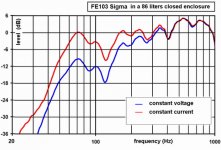
I followed quite the same method with a simple FE103sigma loaded in a 80liters closed enclosure and obtained by current drive a very linear frequency response with no resoance peak and a low cut-off frequency (lower than 55Hz).
Best regards from Paris,
Jean-Michel Le Cléac'h
No, the examples taken in Nelson Pass are real measurements.
Only the elements of the correcting RLC equalizer (for HF correction mostly) are obtained by simulation from the impedance curve
Nelson Pass: "Now that you have an overview of the interface network, let's look at the individual drivers in more detail. In the following pages, you will see a picture of the driver, an impedance curve,
the near and far field response curves for the loudspeaker in the box described above. The dotted line is driven by a voltage source and the solid line is a current source with the parallel
network in the above table."
I followed quite the same method with a simple FE103sigma loaded in a 80liters closed enclosure and obtained by current drive a very linear frequency response with no resoance peak and a low cut-off frequency (lower than 55Hz).
Best regards from Paris,
Jean-Michel Le Cléac'h
Jmmlc said:
I followed quite the same method with a simple FE103sigma loaded in a 80liters closed enclosure and obtained by current drive a very linear frequency response with no resoance peak and a low cut-off frequency (lower than 55Hz).
Best regards from Paris,
Jean-Michel Le Cléac'h
Jean Michel:I modelled that enclosure using the figures here for the FE103 Sigma and estimated it's Vas as 7 liters based on Fostex's other models.
At 80 liters, your box was more than 10 times the Vas and could be considered a true infinite baffle with very similar performance to an infinitely sized box.
The box's Qtc turned out to be 0.33, and with a constant voltage amplifier the model showed it to be 12 dB down from the midpoint at 55 Hz, (3 dB down at 198 Hz). And you say that it worked out to be -3 dB at 55 Hz with constant current drive amplifier? Quite an increase in bass performance.
If I may, more questions on the constant current drive amplifier you used. What was it's output impedance? Was it a specially built amplifier to be current drive or a voltage amp with a large resistor in series, and if so what was the size of the resistor?
I am trying to get a handle on current drive and bass response here.
Hello,
I used for that measurement a tube amplifier with a design of mine to which I gave the name "Shabda". The output tube is a screen driven power tetrode.
Its measured output impedance is 63 ohms.
You can see that amplifier here:
http://www.arduman.com/aa/Sayfalar/lecleach/lecleach.htm
direct picture of the amplifier (on top) with some information:
http://www.arduman.com/aa/Sayfalar/lecleach/08.htm
Best regards,
Jean-Michel Le Cléac'h
Attachments
Jmmlc said:In the message
http://www.diyaudio.com/forums/showthread.php?postid=1077309#post1077309
Svante said:
"This is because most speakers are designed for a 0 ohm driving impedance."
In fact this is only true for enclosures. ...
I feel it's important to add ... Actually, it also greatly affects the cross-over.
In typical x-over parallel networks of speakers designed to be driven by low impedance amps, the amp's impedance is dropped from the equation as it is 'insignificant' relative to the speaker's impedance. The x-over is designing to work at a particular frequency based solely on the impedance of the speaker, ignoring the amp's source impedance.
Enter, a high impedance source. In that case, the amp remains in series with the driver, but the impedance of the amp is no longer insignificant. If your amp has a 50 ohm output impedance, you need to use the combined impedance of 50 ohms + the speaker's impedance when calculating your values for L C & R in your crossover network for it to operate at the correct frequency.
This can also account for why people say constant-current amplification "sounds funny"; as they are using it with speakers designed to be driven by an amp with no appreciable output impedance. And can also account for driver damage if they press-on and decide let's see it it sounds better if I turn it up...
(as the nicely designed networks are no longer crossing over anywhere near where they need to be)I can see why constant-current amplification ends up limited to use with full range drivers, or bi- or tri- amplification, or the 'diy crowd'. Imaging is speaker mfgrs had to design a different crossover for every different amp's output impedance...

p.s. I wish I had a few of those amps of yours you just linked to Jean-Michel !!!
Fabulous.- Status
- This old topic is closed. If you want to reopen this topic, contact a moderator using the "Report Post" button.
- Home
- Loudspeakers
- Multi-Way
- Impedance and current-source amplification