@ eduard,
Perfect 450F MAXWELL BCAP0450 P270 S18 ultra capacitors for UcConditioner solutions is here:
https://www.diyaudio.com/forums/pow...po4-battery-power-supply-146.html#post6647211
There will be no difference if you can also re-assemble the input/output terminal connector to the other side.
Ian
Perfect 450F MAXWELL BCAP0450 P270 S18 ultra capacitors for UcConditioner solutions is here:
https://www.diyaudio.com/forums/pow...po4-battery-power-supply-146.html#post6647211
There will be no difference if you can also re-assemble the input/output terminal connector to the other side.
Ian
Last edited:
Hello Ian,
Me, i wouldnt mind that much if things must be done a little different because in the end it will work perfectly as well.
But there are people who will say why did you mount the caps not according to the manual.
With the stationpi and the raspberry i will not use the specially designed supercap board but it will use the '' normal '''5 volt UcConditioner board with higher F
I will make a '' tower '' of 2 or 3 aluminium boards that will be kind of '' interconnected '' by 4 axes/ longer stand offs or threaded rods positioned close to the outside.
The one at the bottom will be used to mount the lifepo4 board.
The one above that will have two holes above the LCD screen and the cooling block.
It will also have the holes to mount the Station pi board in the position that will give a short connection from the 3,3 volt terminals on the Fifopi, the Reclockpi , the two STS boards from Andrea to the 3 terminals on the lifepo4 board.
To the right side of the station pi there will be space to connect the 3,3 volt UcHybrid boards to the J20 and J25 terminal
To the left side of the Station pi there is less space for the UcHybrid board connected to the J24 terminal. I want to be able to move the tower inside my DDDAC chassis so the the wide of the aluminium will be the same as the lifepo4 board. On the right side the UcHybrid boards can be mounted with normal stand ohh
On the left side it could be necessary to mount them partly above the J5 terminal on the Station Pi board just by using two longer stand offs mounted on the aluminium panel.
This will be rigid enough. If not i will make something like 30 mm PTFE 8 mm axis with thread holes on each end. 2,5 mm standoff is not to strong but as long as you dont touch it it will stay foot!
Above the raspberry there will be the 5 volt UcConditioner board mounted similar style to the 3,3 volt UcHybrid board on the left.
I think when everybody is talking about the immense advantage of the batteries and the supercaps they should also focus on SHORT connections.
THAT is what the French did when they start using the battery supplies for the mc preamp and the power amps with those famous big caps back then.
They almost wrote an instruction how to maintain the advantages of the power supply.
Greetings, Eduard
For the present, 325F perfectly acceptable.
Going forward, having 450F as an option would be pretty awesome for the 12V-16V UcConditioner.
I think I'm going to revert back to the RPi for the I2S feed. None of the USB to I2S solutions interest me ATM. With the addition of Andrea's clock, it's more optimal to separate the PC build as a separate project than to integrate with current project.
It's better to run a separate Andrea's clock dedicated just for USB and running directly to USB DAC.
PC build w/ Andrea's clock for USB -> USB to I2S device -> FiFo w/ Andrea's clock not optimal so need to separate.
EDIT: Not aware of the 325F stock issues. Ouch. That's why having another possible product in the 450F is helpful.
Going forward, having 450F as an option would be pretty awesome for the 12V-16V UcConditioner.
I think I'm going to revert back to the RPi for the I2S feed. None of the USB to I2S solutions interest me ATM. With the addition of Andrea's clock, it's more optimal to separate the PC build as a separate project than to integrate with current project.
It's better to run a separate Andrea's clock dedicated just for USB and running directly to USB DAC.
PC build w/ Andrea's clock for USB -> USB to I2S device -> FiFo w/ Andrea's clock not optimal so need to separate.
- RPi, FiFo w/ Andrea's clock (present)
- PC Build w/ Andrea's clock for USB (future)
EDIT: Not aware of the 325F stock issues. Ouch. That's why having another possible product in the 450F is helpful.
Last edited:
Hello,
But if you will have to put a number of 2,7 volt rated caps in series to get a '' unit '' that will work safely to supply Andrea's clock safely with 16,5 volt you better go higher than 450F. If i remember well there are caps with identical diameter but quiet higher that will give you 700/800 F .
BUT as far as i know right now you can make 16,5 volts by putting lifepo4 in series but then each 3,3 volt cel has to get his own 3,3 volt UcHybrid board.
THAT is the reason i decide to go for the supercap only using a 61,7F 18 volt Eaton. Doede ( the DDDAC man) will make a CC charger which will monitored and switch off and then an '' audiophile style supply '' will take care of the current needed for the clocks.
Greetings, Eduard
Hi,
That's what is great about Ian's solutions is the flexibility. You can choose 325F, 450F or 3000F.
There has to be a sweet spot balance unless you want an extreme build which only offers minimal if any improvement. You need to balance the supply (what Mouser offers), with reliability (Maxwell) and risks (hacking versus proven and trusted Ian solutions).
That's great if one chooses to hack a Super Cap solution. In my case, I want a trusted solution which only Ian provides. He eats, sleeps and dreams about power solutions. I would not trust a hack. I value safety and risk of property loss too much. But that's what great about this hobby, everyone can weigh the pros and cons to suit their needs.
IMO, it's just an unnecessary complication which will make performance worse not better as Ian's products are proven, well-tested and fully optimised. Not taking into account all the unnecessary risks your exposing yourself to for either worse performance or minimal at best. Hack is an easy pass in this case.
Last edited:
Hello,
The 61,7 F cap is from a reputable manufacturer and will be delivered by Mouser. It has a built in " system" to get equal voltages on all the six caps mounted in series.
Doede will design the charger and the circuit that can be set to the moment when the audiophile supply will take over.
I am sure Doede can make a perfect solution for this.
Greetings,Eduard
Hi,
I wish you luck with that solution. I understand the urgency because of the honeymoon period with Andrea's clock.
For my case, I won't be able to permanently implement Andrea's clock till end of the year so I prefer to wait for a Ian solution.
For power solutions, I only trust Ian. For clocks, I only trust Andrea. For DACs, I only trust Rob Watts (Chord Electronics). I'm sure each may have general knowledge of each area, but they all have their specialty. I lean towards their specialties only since they spend decades refining that area of their craft.
I'm sure each can hack something that's not their specialty, but as a consumer I rather focus on what they dedicate to their life's work. Especially when it comes to power safety regulations and standards. One misstep and you can lose your entire house and invaluable possessions all for a possibly non-existent improvement over 325F.
I rather have the power solution by someone that's thinks about this 24/7, not someone reading about it for a few hours to put together a hack.
Cheers
Last edited:
Hello,
The thing i asked Doede to build is a bit more basic because i am using a cap composed by 6 caps in series that already has the circuit inside to make it work like an 18 volt cap.
So Doede will make a CC charger which is pretty much a simple thing.
A circuit based on Arduino that will monitor the voltage on the caps and that will decide when the time has come to change from one supply to the other one which will basically supply the current needed for the circuit plus necessary headroom.
Doede is surely capable of making such a set up without even glancing how Ian has done his design.
Greetings, Eduard
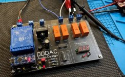
here it is, working fine.
Has nothing to do with Ian solutions, which are very good by the way and plug and play
It is just a management module to quickly charge a UC bank (up to 20Volt) through an external charger (10 A or so) and than switch back to the audiophile PSU which is also externally connected. The module will disconnect the charger and de-power its mains.
The UC Bank should be connected directly at the VB input of the user. Which I believed to be of advantage looking at the concept why a UC helps sound quality (shunt close to user) I know some see this critical for safety reasons, so you can still ad a thick 2 pole switch and disconnect the UC bank when not in use. Up to the user of course
It is a general module where the switch voltage can be set by DIP switches. Nice for experiments (like I do now) or in use with other gear (DDDAC 12 volt supply or Clocks/PCs with 15-18 Volt)
But I am not asking anyone to use this or risk their homes. BTW, DIY always carry risk. No need for UCs for that. If I see all that gear with no safety earth, you might dangle dead to your next tube amplifier as well
any way, here is a pic:
Probably to much Off Topic, I will start an own thread where we can discuss further if you want (in power supplies)
.
Attachments
Last edited:
I admire the passion for the solution. Please let know impressions with Andrea's clock once things are up and running.
Because of the nature of Super Caps and the risks involved, I'm good to standardise with a Ian solution. I already have 3 3.3V UcHybrid, 1 5V UcMate, 1 3.3V UcConditioner and 1 5V UcConditioner so I don't want to mix solutions. A 12V or 16V UcConditioner will blend in nicely. Especially if you have the option to stack on top of MKIII.
I'm not running a lab, but just a simple consumer setup where I have the weigh the risks of points of failures.
My higher priority issue now is researching how to loop a semi-rigid cable around or through the TransportPi after ReClockPi for Andrea's clock.
I do though look forward to impressions with the Super Caps in the mix.
My end game goal when I looked into this DIY hobby was to max out the clock with Ian's solutions. I can see the finish line with Andrea's clock, but still have some DIY hurdles to overcome.


Hi Ian,
I would like to built a streamer with following setup:
LinearPi dual
Conditioner 3.3 and 5
Receiverpi
Transportpi
FifoPi
Raspberry 4 for Moode
With spdif connection to active Dynaudio speakers
The receiverpi will be used for toslink connection from the TV. I worry about lip sync issues using the toslink connection. Will this setup work without lip sync issues?
Hi,
I want to build a streamer to be integrated in my pre amp.
Base would be an RPI 3b/4.
stationpi
fifopi Q3
reclockpi
dual linearpi 3.3V and 5V
conditionerpi
uc conditioner 3.3V
This will be cobbled to a dam1941.
Is this correct? do i need anything else / different?
What will be the most use full clock speed for the dam1941?
regards,
John
Hi Ian,
I would like to built a streamer with following setup:
LinearPi dual
Conditioner 3.3 and 5
Receiverpi
Transportpi
FifoPi
Raspberry 4 for Moode
With spdif connection to active Dynaudio speakers
The receiverpi will be used for toslink connection from the TV. I worry about lip sync issues using the toslink connection. Will this setup work without lip sync issues?
FifoPi has default 0.2s delay. I'm not sure if that can be a lip sync issue?
Ian
Hi,
I want to build a streamer to be integrated in my pre amp.
Base would be an RPI 3b/4.
stationpi
fifopi Q3
reclockpi
dual linearpi 3.3V and 5V
conditionerpi
uc conditioner 3.3V
This will be cobbled to a dam1941.
Is this correct? do i need anything else / different?
What will be the most use full clock speed for the dam1941?
regards,
John
Please see my reply at here:
https://www.diyaudio.com/forums/dig...mate-weapon-fight-jitter-662.html#post6675978
Hi Ian,
How big is the difference?
It is almost impossible to fit 2 of the conditioner, 1 barely fits (close to stationpi that is). The conditionerpi is a lot compacter.
The conditioner pi is only feeding the rpi, yes?
anything on the clocks?
Regards,
John.
How big is the difference?
It is almost impossible to fit 2 of the conditioner, 1 barely fits (close to stationpi that is). The conditionerpi is a lot compacter.
The conditioner pi is only feeding the rpi, yes?
anything on the clocks?
Regards,
John.
Last edited:
- Home
- Group Buys
- Ian asynchronous I2S and S/PDIF FIFO KIT group buy