
Bruno, what considerations lay behind choosing the value of the capacitor placed between + speaker terminals on bridged Ncores? I think you said above that you would put the value at 150nF.
This is to keep keep the both amps in sync during switching. The cap must be placed close to the modules.
Thank you, J-P. J-P or Bruno, I want to experiment with replacing the Mylar capacitors in the output filter. I know that by doing so I will likely increase inductance etc., but apart from those valid concerns, are these capacitors removeable and replaceable? I'm wondering if soldering a replacement cap might not contact appropriate of the sandwiched layers of the board, if you catch my meaning.
Are there any fundamental, objective reasons why bridging the ncore amps would improve their performance (not just increase the power) so as to improve the sound?
No.
That's kind of what I thought...Would be interesting to hear Bruno's take on this comment which was posted on another forum:
"...I don't have a clear understanding of the topology of this amplifier yet, but it seems to me that bridging should give greater power supply noise reduction. By power supply noise, I mean anything entering, riding on or produced by the main output or any of the power rails---whether RFI/EMI picked up from god knows where, voltage variations emitted by the switching elements of the supply, variations created by current draws passing from a positive-impedance, dielectric absorption voltages from the ugly output and supply electrolytics, various resonances and instabilities---all of which exist dynamically in a complex state of constant movement and flux (simplistic sine-wave analyses don't come close to modeling this stuff). I'm speaking here of the entire gamut of AC existing on the power rails, which should be pure DC. Subject to limited feedback reduction, that noise will pass 1:1 through the Ncore FETs into your speakers into the air into your ear. ....."
"...I don't have a clear understanding of the topology of this amplifier yet, but it seems to me that bridging should give greater power supply noise reduction. By power supply noise, I mean anything entering, riding on or produced by the main output or any of the power rails---whether RFI/EMI picked up from god knows where, voltage variations emitted by the switching elements of the supply, variations created by current draws passing from a positive-impedance, dielectric absorption voltages from the ugly output and supply electrolytics, various resonances and instabilities---all of which exist dynamically in a complex state of constant movement and flux (simplistic sine-wave analyses don't come close to modeling this stuff). I'm speaking here of the entire gamut of AC existing on the power rails, which should be pure DC. Subject to limited feedback reduction, that noise will pass 1:1 through the Ncore FETs into your speakers into the air into your ear. ....."
Are there any fundamental, objective reasons why bridging the ncore amps would improve their performance (not just increase the power) so as to improve the sound?
Yes.
Hahaha...
Maybe, but I doubt it...
Are there any fundamental, objective reasons why bridging the ncore amps would improve their performance (not just increase the power) so as to improve the sound?
Maybe, but I doubt it...
Yes.
I'm pretty sure Bruno said that it wouldn't change the amplifier sonically.
Seems we have a difference of opinion. We have a yes and a no, but no reasoning to support either opinion. Hopefully Bruno will address the issue directly at some point....I am assuming that at some point Hypex put the ncore in bridged mode and tested them, both on the bench and with their ears.....
I'm pretty sure Bruno said that it wouldn't change the amplifier sonically.
Perhaps. Can we merely assume that noise on the +/– output rails of a single Ncore is mirror-equivalent or more closely matched than noise exiting two Ncore modules operating in bridge? That's the salient question, imo.
Here's my thinking about the comparator. I'll give this despite my cursory understanding of comparator electronics; the thinking seems valid all the same. The comparator is the device (or chip or circuit stage) that renders the analogue signal digital. Post the comparator, that signal is a PWM codification of the original analogue signal. That codifying process is therefore, like any digital audio process, subject to jitter.
Being so, I want to provide ultra-quiet DC power to the comparator.
Somewhat serendipitously, I ran across this today. This is Hervé Deletraz speaking about his early (presumably class D) investigations (interview here):
I know Hervé's perspective is rather opposite yours on many aspects of audio playback. I'm not bringing him in here to raise those differences (re feedback etc). I just happen to agree with him on the importance of jitter as it relates to the comparator's function in digitizing the signal.
Being so, I want to provide ultra-quiet DC power to the comparator.
Somewhat serendipitously, I ran across this today. This is Hervé Deletraz speaking about his early (presumably class D) investigations (interview here):
At the time I designed my first digital amplifier, I had to build all the electronics for the analog to digital domain, since such kind of converters didn't exist off the shelf, especially with the level of performances I needed. For a long time – several years - I tried to develop the "perfect" digital amp, but the biggest problem was the residual noise due to the clock jitter, which I wouldn't want to correct using a global feedback – my original 1984 digital amp was already an open loop design – and the biggest problem was the frequency response, dramatically affected by the speaker impedance, due of the use of the output filter.
Anyway I am still thinking about a digital amp, just in order to know what I would be able to do in this new, promising century…
I know Hervé's perspective is rather opposite yours on many aspects of audio playback. I'm not bringing him in here to raise those differences (re feedback etc). I just happen to agree with him on the importance of jitter as it relates to the comparator's function in digitizing the signal.
The pic is not the analogue 'comparator'
Read Bruno's papers to understand what is going on in the amps. I've found him to be very good at his explanations
It's an analogue amp. No processor is involved in the amplification. There is no 'conversion to digital'
It's self oscillating. Something which also happens on the analogue domain
It's worth understanding exactly how the circuit works and exactly how it has been implemented before thinking of 'improving' it. Everything is surface mount for a very good reason
YesAny more votes for this?
I know that in the true spirit of DIY I can and should source crimps and shells myself, but the availability of spare/alternative harnesses or harness components would make life a whole lot easier.
I will be looking for Y harnesses
A spare harness set would have meant that I would have chopped the harness to length in my first lash-up
Alternatively shells and crimps would make it easier for me to make my own custom harnesses - and/or to modify the existing psu harness
Indeed the PIC is not in the audio signal!
The amp is a full discrete design, no chips used in the signal line....
Please be very carefull with tweaking, the design is optimized for very low EMI and obvious very good audio performance. Adding or changing components will have high risk to influence the performance. For sure changing the output caps. Caps what will not be a drop in replacement or with longer leads as 0,5mm is a no-go....
Everybody and his cousin mounts TO220s without heatsinks, in spite of the 85% or so reduction in rated dissipation. So the heatsink police won't come knocking at your door... this time.
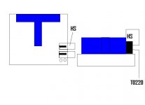
Any harm in adding some heatsinks? I was thinking clip-on types with one half cut off, so that it presents a vertical profile to the board components (read: doesn't overhang anything). Are the heatsink tabs grounded? do they need to be isolated from one another? I hope the attached diagram makes it clear.
Attachments
The pic is not the analogue 'comparator'
Read Bruno's papers to understand what is going on in the amps. I've found him to be very good at his explanations
It's an analogue amp. No processor is involved in the amplification. There is no 'conversion to digital'
It's self oscillating. Something which also happens on the analogue domain
It's worth understanding exactly how the circuit works and exactly how it has been implemented before thinking of 'improving' it. Everything is surface mount for a very good reason
I understand the basics of this amp. Yes, the amp is self-oscillating etc. The pulse-code that emerges from the comparator is a digital representation of the analogue signal. Surely you're not saying the PWM codification cannot be better characterized as digital? It is, imo, no different than a PCM "signal" which, in the sense I'm speaking here, is for its part carried as an analogue waveform that can be viewed as such on a scope.
Indeed the PIC is not in the audio signal!
The amp is a full discrete design, no chips used in the signal line....
Please be very carefull with tweaking, the design is optimized for very low EMI and obvious very good audio performance. Adding or changing components will have high risk to influence the performance. For sure changing the output caps. Caps what will not be a drop in replacement or with longer leads as 0,5mm is a no-go....
Thank you, J-P. I understand concerns about EMI and risks about deleteriously impacting performance.
- Status
- Not open for further replies.
- Home
- Amplifiers
- Class D
- Hypex Ncore