What do you guys think as far as grain direction on a finished center channel speaker? Do you think the grain should run top to bottom on the front (vertically), considering its horizontal arrangement, or side to side (horizontally)?
All of the grain will be vertical on the mains, of course.
I'll be using real wood veneer or woodgrain laminate, I have not decided yet. In either case, the grain will be prominent.
I'd definitely suggest you spend the extra dollars on real wood veneer - unless your choice is something extremely exotic they probably won't cost much more then a realistically wood-grained plastic laminate, and while the iron-on method does take a little longer than contact cement, you have all the working time you need for perfect grain alignment / matching.
and the plastic laminates look like it
Hi Chris - I'm sure you are right - was looking at a Wilsonart Mahogany Laminate.
Shop Wilsonart 48-in x 10-ft Empire Mahogany Laminate Countertop Sheet at Lowes.com
Of course, PE sells a few that are pretty well regarded:
Cherry Vinyl Laminate 2 ft. x 18 ft. 261-614
The thumbnail always looks good of course.
But, I have my doubts that it would look like a craftsman built them when all is said and done. Maybe it would pass muster at a glance.
The attractive thing about them is that the finish is already done.
I believe everything will fit on one sheet of 4x8 wood veneer.
The layout will be something like this:
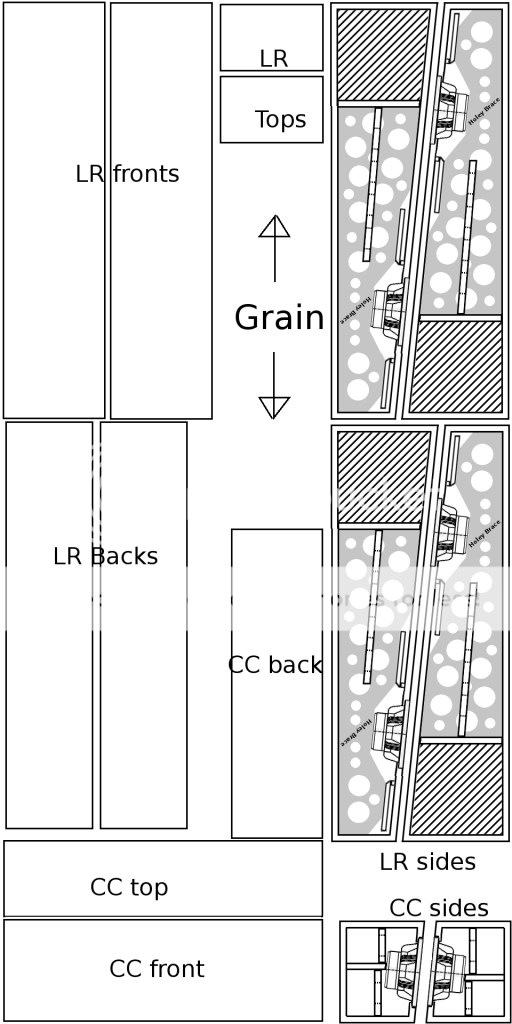
I think there will be just enough room to cut the pieces a smidgen larger than necessary so that the 1/4" downward cut spiral flush trim bit can handle the final cut to the exact size of each panel after adhering the veneer.
The grain direction will be top to bottom on the front and sides of the speakers, and I guess front to back on the tops. If you guys think the grain should run side to side on the tops, let me know soon.")
I don't think there is room to cut the back piece of the center channel in the correct grain direction, but, as it will never be seen, I think running it the wrong way is OK. The mains will have the grain the correct orientation even on the backs though.
I plan to run strips of scrap veneer along the back edges (removable back panel) rather than applying one piece to the back and trying to glue the whole thing on and then cut a slit so that the removable panel, could be, you know, removed. I think that method would result in me gluing the whole thing together permanently by mistake. So, I'll just use strips.
No veneer for the speaker bottoms on the layout, but I might have enough material to do it. Low priority.
The layout will be something like this:
I think there will be just enough room to cut the pieces a smidgen larger than necessary so that the 1/4" downward cut spiral flush trim bit can handle the final cut to the exact size of each panel after adhering the veneer.
The grain direction will be top to bottom on the front and sides of the speakers, and I guess front to back on the tops. If you guys think the grain should run side to side on the tops, let me know soon.
I don't think there is room to cut the back piece of the center channel in the correct grain direction, but, as it will never be seen, I think running it the wrong way is OK. The mains will have the grain the correct orientation even on the backs though.
I plan to run strips of scrap veneer along the back edges (removable back panel) rather than applying one piece to the back and trying to glue the whole thing on and then cut a slit so that the removable panel, could be, you know, removed. I think that method would result in me gluing the whole thing together permanently by mistake. So, I'll just use strips.
No veneer for the speaker bottoms on the layout, but I might have enough material to do it. Low priority.
Ben:
A few observations, if I may;
Depending on the degree of figuring and width of individual stitched flitches on the sheet, and your plan for wrapping of grain matching, the break out of material may not work out as efficiently as you've drawn.
For example, I've built quite a few pairs of FH3, and while the total surface area isn't that great, due to their shape, and my own aesthetic, a highly figured pattern such as Cherry or Walnut won't leave a lot of usable material left from a full sheet, while something like rift/quarter cut oak, any of the reconstituted types ( Alpi, etc), or tight patterned ribbon grain Sapele, will.
In the case of the FH3 you could wrap the pattern horizontally in a "butterfly" shape, but that can present an issue if the grain figuring varies substantially along the length, as well as the alignment of pattern on the top, which would be highly visible.
I generally prefer the grain wrapped contiguously around the visible panels of the circumference, as well as mirror the mains.
Other folks wrap grain from the front to top, which results in the sides and tops meeting at right angle. - without consulting the AWMAC specifications for Premium Custom grade, there is probably no "right" way about it
Whatever alignment pattern you chose, you definitely want to band the edges first, so that the sides & top overlay them. After that, I'd veneer the fronts, backs if you will, then the sides, and the tops / bottoms last.
I find each sheet of veneer "speaks" to me in terms of how to center and wrap the grain pattern around the enclosures and match the larger mains. That often throws a highly efficient cut plan out the window.
I often don't bother veneering the backs of floorstanders or centers for that matter, and paint them with something like Rustoleum Accent Stone finish.
Thanks for sharing your experience, Chris, it's very helpful. I'm just trying to avoid having to purchase more than one sheet as it will possibly cost well north of $200.00 US per sheet. I'm thinking of using either a colorful exotic species and clear coating or using a pre-finished veneer from Treefrog. The Treefrog option is a composite wood product so matching and aligning will probably be less of an issue. Either way I won't have to worry about blotchy absorption of dye, and related finishing issues.
Last edited:
Thanks for sharing your experience, Chris, it's very helpful. I'm just trying to avoid having to purchase more than one sheet as it will possibly cost well north of $200.00 US per sheet. I'm thinking of using either a colorful exotic species and clear coating or using a pre-finished veneer from Treefrog. The Treefrog option is a composite wood product so matching and aligning will probably be less of an issue. Either way I won't have to worry about blotchy absorption of dye, and related finishing issues.
Sticker shock for me on the veneer price - of course working in the trade, I enjoy substantially lower cost than that on my most frequent species (well less than $80).
How would you plan on adhering the prefinished veneer? 'cause the iron-on method isn't gonna work. I've never worked with the PSA self adhesive veneers - they may work great for panels, but I can only imagine that grain alignment around enclosures such as yours could be at least as tricky as contact cement - in other words, no margin for error.
Sticker shock for me on the veneer price - of course working in the trade, I enjoy substantially lower cost than that on my most frequent species (well less than $80).
How would you plan on adhering the prefinished veneer?
Yes, it's expensive. I can get unfinished paper backed cherry locally (4x8) for $80 plus tax. But, finishing it would be tricky to get it to be colorful (I can't say I'm too excited about tan colored speakers). So, for the saved time and cost of finishing products (I don't have much on hand), I'm guessing it might be worth the extra $150. I'll have to think on that a little more I suppose.
Assuming the pre-finished composite veneer, I'm thinking of just cutting it a little larger than the size of the panel to cover with tin snips and then gluing it on with vinyl tile adhesive applied with a foam roller. Then, I'd clamp a piece of plywood on top of it to press it. Then, after a day or so I'd take the clamps off, trim the veneered side with my router and proceed to do the next side.
If I end up with regular paper backed, I'd use the iron method or a scraper if I went with the riskier contact adhesive or pressure sensitive adhesive (PSA) way. (Yes, PSA is just as bad as contact cement as far as repositioning, but you can inch back the liner and scrape as you go to minimize bubbles.)
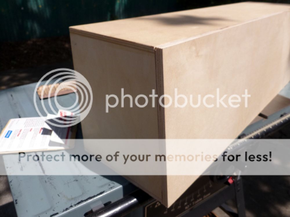
I finally had a few hours to spend on this!
So, here's what I got done:
First, I installed approximately 1" wide cleats inside the back lip of the center channel cabinet. I made sure to get the fit perfect, avoiding any gaps:
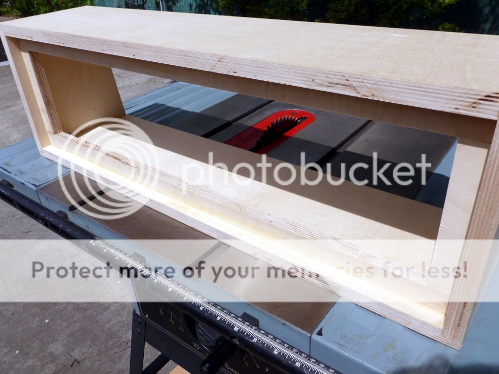
Next, I trimmed the removable back panel to fit. It is perhaps a bit too snug in the middle due to some downward bow in the middle of the top panel, but I did not want any large gaps. I plan to use some nice "T" nuts and stainless button head machine screws that I have on hand to secure it at a later time. If the back is too difficult to remove in the future, I'm sure I can get it out by patiently taking some larger screw(s) and inserting them into the holes and wiggling it a bit. Here's a picture of the back inserted:
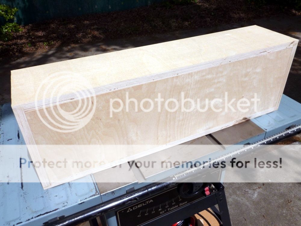
After that, I routed a rabbit all around the edges of the front panel to nest into the cabinet for a better/stronger joint:
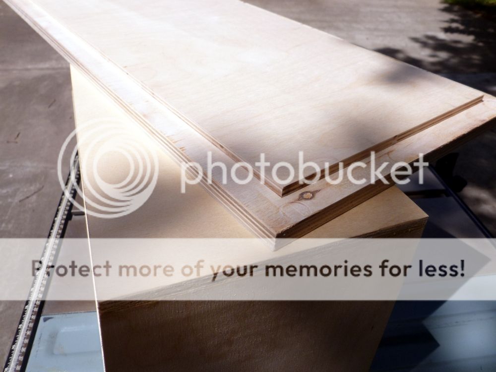
I trimmed the top and bottom edges to the correct angle. Here it is dry fit:
Hard to see that 5 degree angle in photos for some reason - it is much more apparent in person.
The next thing I'm currently puzzling over is how/if I should fix the downward warp (about 1/16") of the top panel. The reason I may want to fix it is because the front panel is a little bit taller then the top in the middle. The veneer needs a smooth substrate, obviously. So, I'm probably going to either try to wedge something in between the top and bottom while gluing the front on, or, alternatively, using a filler product to smooth it out, which might be best as I think a wedge with sufficient force to budge it might risk ripping away the glue joints at the sides - although it is really well glued. I suppose I could add clamps for good measure if I go with the wedge.
By the way, I bought quarter sawn Ash veneer (much nicer than the usual flat cut) and will use some purple transtint dye on it to make a pseudo Purpleheart that won't have the issues with retaining its color long term.
So, here's what I got done:
First, I installed approximately 1" wide cleats inside the back lip of the center channel cabinet. I made sure to get the fit perfect, avoiding any gaps:
Next, I trimmed the removable back panel to fit. It is perhaps a bit too snug in the middle due to some downward bow in the middle of the top panel, but I did not want any large gaps. I plan to use some nice "T" nuts and stainless button head machine screws that I have on hand to secure it at a later time. If the back is too difficult to remove in the future, I'm sure I can get it out by patiently taking some larger screw(s) and inserting them into the holes and wiggling it a bit. Here's a picture of the back inserted:
After that, I routed a rabbit all around the edges of the front panel to nest into the cabinet for a better/stronger joint:
I trimmed the top and bottom edges to the correct angle. Here it is dry fit:
Hard to see that 5 degree angle in photos for some reason - it is much more apparent in person.
The next thing I'm currently puzzling over is how/if I should fix the downward warp (about 1/16") of the top panel. The reason I may want to fix it is because the front panel is a little bit taller then the top in the middle. The veneer needs a smooth substrate, obviously. So, I'm probably going to either try to wedge something in between the top and bottom while gluing the front on, or, alternatively, using a filler product to smooth it out, which might be best as I think a wedge with sufficient force to budge it might risk ripping away the glue joints at the sides - although it is really well glued. I suppose I could add clamps for good measure if I go with the wedge.
By the way, I bought quarter sawn Ash veneer (much nicer than the usual flat cut) and will use some purple transtint dye on it to make a pseudo Purpleheart that won't have the issues with retaining its color long term.
Last edited:
Cutting the holey brace now - pretty tricky. I've so far cut the piece to the exact width of the inside of the cabinet (it's a tight fit), notched out the back corners to clear the cleats, and cut the angle into the front edge so it will fit perfectly against the back of the front panel.
Next up will be to cut out the middle of the brace to fit exactly behind the driver and slot vents. I suspect I will need to work a bit on the front baffle first. So I'll put this piece aside.
I got in the veneer. Looks good. Will probably apply to the back first! If that looks good, I'll veneer the front panel and then router the driver flange and hole and the slots. Then, cut the pieces that make up the slot vents and attach those to the back of the front panel. At that point, I can start fitting the brace more precisely. That's when I'll resume work on the brace.
A little progress update today -

Beginning to route the driver hole flange in the veneered front baffle.

Completed driver hole with flange.

Perfect fit.
On my Jasper circle cutting jig, the 6-1/2" position worked well for the Alpair 10.2 outer flange boundary (the first cut). Then I routed successively smaller circles to make the flange wider. Finally, the 5-3/8" position worked well for the through hole.
Don't be an idiot like me though and attempt to cut through 3/4" ply in one pass with a router - you will start a fire, as I did. Fortunately I was able to put it out without any real harm done. You might not be so lucky. It's simply too much friction. The solution is to route half way through the stock on the first pass then plunge down through the material on your second pass.
Beginning to route the driver hole flange in the veneered front baffle.
Completed driver hole with flange.
Perfect fit.
On my Jasper circle cutting jig, the 6-1/2" position worked well for the Alpair 10.2 outer flange boundary (the first cut). Then I routed successively smaller circles to make the flange wider. Finally, the 5-3/8" position worked well for the through hole.
Don't be an idiot like me though and attempt to cut through 3/4" ply in one pass with a router - you will start a fire, as I did. Fortunately I was able to put it out without any real harm done. You might not be so lucky. It's simply too much friction. The solution is to route half way through the stock on the first pass then plunge down through the material on your second pass.
Wow, nice! Just curious, is there a rationale for putting the slot vents very close to the driver?
This was the question I wanted to ask!
I was always led to believe a port close to the driver was bad practice leading to midrange leakage and early cancellation to the bass output. My rational is the opposite, locate the port as far as possible from the driver. (whether what 'i have been led to believe' is fact, or just an author specific opinion, i couldnt say. However, i have never liked the outcome of close port location, when i have tried it.
It is the only thing I dislike, the rest is awesome.
Last edited:
This was the question I wanted to ask!
I was always led to believe a port close to the driver was bad practice leading to midrange leakage and early cancellation to the bass output. My rational is the opposite, locate the port as far as possible from the driver. (whether what 'i have been led to believe' is fact, or just an author specific opinion, i couldnt say. However, i have never liked the outcome of close port location, when i have tried it.
It is the only thing I dislike, the rest is awesome.
Thanks for your question - the port slot openings inside the cabinet are well away from the driver so there will be no midrange leakage. Take another look at the plans. The locations and double slots help prevent this from becoming a transmission line.
I see what you mean, and it may reduce any TL behaviour, I wasnt commenting on that.
If I were to comment on the slots: They're ok. Id ask if you exceeded the old rule of thumb (is it 7:1 or 8:1?) regarding aspect ratio? But I hadn't noticed that before. That wouldn't necessarily be good (runs off to try and check the dims), but I wasn't really trying to be picky
No, what I meant was something I picked up somewhere read, heard, otherwise thought to be true
This something being that the port distance from the driver effects roll off rate in Ported systems. i.e. The larger the distance the lower the threshold frequency where the sub-Fs port output cancels the front output. This continues in the belief that a port in close proximity to a woofer can have problems in the upper bass or mids due to reflection (no worries I think you're okay there), but you might have a slightly more rapid roll off below Fs, than with the port the furthest you can get it (although that would probably encourage TL behavior in a suitable shape box
I would still worry a little about the vent aspect ratio (i would have split them 'Onken style') but GM in post #7 (having re-read) seems to answer what I talking about (and know a great deal more about it) Im still not sure I like the ports so thin...(sorry it's just me) but it just looks cool
Like I said though, it was a small thing....Great looking design and quality build so far.
Last edited:
Like I said though, it was a small thing....Great looking design and quality build so far.
Thanks for your follow up and participation in the discussion! I appreciate it.
The inner terminus of the ports are probably farther away from the back of the driver than many bass reflex designs out there. Forgot to mention that in my earlier post....
I think thin ports are OK - it's certainly something common among many designs commercial and DIY. The vent wind speed should be low as well according to the figures. These are *very* thin at 1/4" but wide so the overall opening is quite large.
As the width of the port is 7" and the inside of the cabinet is 8" I can certainly put a filler piece/divider in the middle of the slot passageway and cut the slot a bit wider, if everyone thinks that would sound better? Obviously, I was going to use some filler strips at the sides anyway to restrict the port width to the 7" past the baffle. This extra material removed might come at the cost of a slight loss of strength for the front baffle however.
Last edited:
High aspect ratio vent is less sensitive to dynamic changes on the driver parameters (and thus the tuning)
dave
Thanks Dave! Would you suggest leaving them as is or changing them? Now is the time as I have not cut them yet.
So I can have either four vents 2.83" x 1/4" or two vents 7" x 1/4".
- Status
- This old topic is closed. If you want to reopen this topic, contact a moderator using the "Report Post" button.
- Home
- Loudspeakers
- Full Range
- HT Front Stage Designs Using Markaudio Alpair 10.2 - Plans, Feedback and Build Log