I just put the TMC resistor on the amplifier output side and not the NFB point side. Then I plottet the amp output. My LG plot seems ok that way and it matches what he wrote about the 0 dB point. When I compare his way of inferring OLG and his way of plotting LG, the gain crossover from the OLG plot and the point where the LG reaches 0 dB matches more or less exactly, both being around 500 kHz. This is how it is supposed to be.
In my view that more or less validates the 2 methods on plotting OLG and LG.
Same way how I did firt time, but I am not sure that in this way TMC was put in the picture.
dado
Compare these 2.
OLG and LG.
OLG gain crossover and LG 0 dB point match more or less.
The difference being around 10 kHz, due to measurements inaccuracies and the fact that the plotting methods for both OLG and LG arent 100% accurate, they are just very close approximations.
How you did OLG, where Middlbrook probe was, or you used inductor?
How you did OLG, where Middlbrook probe was, or you used inductor?
Changed my 21K5 resistors in my NFB to 1Meg, as per Cordell. See Inferring loop gain, page 415, bottom. It is not accurate below 10 kHz but above it is reasonably accurate.
See picture.
Attachments
Last edited:
Changed my 21K5 resistors in my NFB to 1Meg, as per Cordell. See Inferring loop gain, page 415, bottom. It is not accurate below 10 kHz but above it is reasonably accurate.
See picture.
Why you don't use Middlbrook probe as you did in other thread, it is accurate below 10kHz?
Why you don't use Middlbrook probe as you did in other thread, it is accurate below 10kHz?
Well, if I simulate OLG with Middlebrook probe, the OLG gain crossover and LG 0 dB point dont match. However, if I use the OLG method as Cordell described it, the OLG gain crossover and LG 0 dB point more or less match.
Also, look at the weird phase swings, that cant be right either.
This leads me to believe that there is something wrong with the Middlebrook probe method, most likely that it doesnt work correctly with TMC.
I'm by no means an expert in this, but it seems to be the logical conlusion.
Last edited:
Another thing, if you use Middlebrook probe with regular miller compensation you get some rather interesting results as well, you not only get phase without weird phase dips, but you also get a gain plot that looks very close to a LG plot and not an OLG plot.
Does the middlebrook probe method show LG and not OLG?
Does the middlebrook probe method show LG and not OLG?
Another thing, if you use Middlebrook probe with regular miller compensation you get some rather interesting results as well, you not only get phase without weird phase dips, but you also get a gain plot that looks very close to a LG plot and not an OLG plot.
Does the middlebrook probe method show LG and not OLG?
I have to think about it and try some more simulation. Cordell way does not do TMC good.
The Middlebrook probe shows OLG.
dado
The Middlebrook probe shows OLG.
dado
Loop Gain Simulation - Frank Wiedmann
It mentions Middlebrook.
You sure it shows OLG?
Hmm, take a look at this.
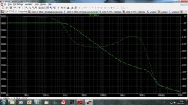
1. LG, Cordell method.
2. Middlebrook method, but with the TMC outside of the feedback, connected to the right side of the AC source inserted in the feedback path. Looks like LG to me.
Look at the 0 dB point, identical, the only difference is Phase, but that is not unusual when you use different methods.
Still sure Middlebrook probe shows OLG? Looks like LG to me.
Attachments
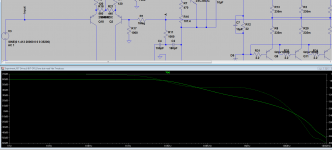
I followed instruction how to measure Loop Gain(negative feedback loop gai) from Cordell's book(page 416) and here is result.
I thing that this method is good for CMC but not TMC. I tried to move inductor to include TMC resistor in to measuring but result is strange.
dado
Sorry,
120 dB of loop gain does not look right. Your 0db x-over is at c. 2MHz if I read it correctly. Can you post your whole circuit?
Hmm, take a look at this.
1. LG, Cordell method.
2. Middlebrook method, but with the TMC outside of the feedback, connected to the right side of the AC source inserted in the feedback path. Looks like LG to me.
Look at the 0 dB point, identical, the only difference is Phase, but that is not unusual when you use different methods.
Still sure Middlebrook probe shows OLG? Looks like LG to me.
This looks a bit more correct. I dont think the differences between your two plots are anything to worry about, as you say.
But, re my previous post, we need to clear up any misunderstandings on OLG, CLG and LG before we can move this thread forward to a successful conclusion.
This looks a bit more correct. I dont think the differences between your two plots are anything to worry about, as you say.
But, re my previous post, we need to clear up any misunderstandings on OLG, CLG and LG before we can move this thread forward to a successful conclusion.
Yes, but now that we know that you should use LG to determine phase and gain margin, I think we are on the right way.
Now determining OLG with a TCM amp, well, that is a good question, Cordells OLG plotting method with 1 Meg resistor isnt accurate until you reach 10 kHz and up.
Here is zip LTspice file with Middlbrook and Cordell .ac
dado
Tried simulating both.
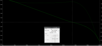
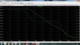
Middlebrook probe, with TMC resistor connected to amplifier output, 0 dB point around 1.675 MHz.
Cordell LG method, with once again TMC resistor connected to amplifier output, 0 dB point around 1.675 MHz.
Looks like they match, although they show a little variation in phase at the 0 dB point, just like my own 2 previous examples.
I guees that for LG the Middlebrook probe might be the best to use, since it will give you a little less phase margin, so when you trim your amp for phase margin you would be more on the safe side with the Middlebrook probe.
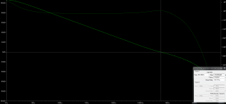
Now it gets interesting. Doing some simulations on my own amp and even ridiculously low TMC values like 10pF+100pF, provide more than enough LG phase and gain margin.
However 20 kHZ square wave test shows it oscillating a little, ringing and overshooting. So it seems that it is relatively easy to get good LG phase and gain margins but the limits to how low you can go should be determined by square wave testing.
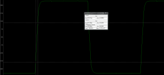
20 kHz square wave testing into a 8 Ohm//2uF capacitor load with TMC of 150pF+180pF and a 1000 resistor shows slight rounding of the edges and no oscillations, overshoot or ringing. Slewrate is at a decent 35V/us.
However at the tops and bottoms of the square wave you can see something that breaks the straight lines a little, what is that, signs of a little instability? Mind you, it is not there without any capacative load parallel to the 8 Ohm load.
THD-1 numbes are insane, 60 Watt, 8 Ohm, 0.0000XX% and it stays there even down to 2 Ohm, that is 240 Watt 2 Ohm, 0.0000xx% THD-1. THD-20 numbers are good as well, 60 Watt, 8 Ohm, 0.000XXX% the same goes for 4 Ohm, 0.000XXX%, rising to 0.00XXXX% THD-20 at 2 Ohm, 240 Watt. I'm impressed and quite satisfied.
However 20 kHZ square wave test shows it oscillating a little, ringing and overshooting. So it seems that it is relatively easy to get good LG phase and gain margins but the limits to how low you can go should be determined by square wave testing.
20 kHz square wave testing into a 8 Ohm//2uF capacitor load with TMC of 150pF+180pF and a 1000 resistor shows slight rounding of the edges and no oscillations, overshoot or ringing. Slewrate is at a decent 35V/us.
However at the tops and bottoms of the square wave you can see something that breaks the straight lines a little, what is that, signs of a little instability? Mind you, it is not there without any capacative load parallel to the 8 Ohm load.
THD-1 numbes are insane, 60 Watt, 8 Ohm, 0.0000XX% and it stays there even down to 2 Ohm, that is 240 Watt 2 Ohm, 0.0000xx% THD-1. THD-20 numbers are good as well, 60 Watt, 8 Ohm, 0.000XXX% the same goes for 4 Ohm, 0.000XXX%, rising to 0.00XXXX% THD-20 at 2 Ohm, 240 Watt. I'm impressed and quite satisfied.
Attachments
Last edited:
However at the tops and bottoms of the square wave you can see something that breaks the straight lines a little, what is that, signs of a little instability? Mind you, it is not there without any capacative load parallel to the 8 Ohm load.
Possibly a result of the output inductor resonating with the load capacitor, causing large current spikes in the OPS.
I did same more tests with Middlbrook probe as in LTspice example "Loopgain" and came to conclusion that it will show Loop Gain not Open Loop Gain. If you want to see OLG it is necessary to set Close Loop Gain to one(1) and the plot with Middlbrook probe. In this case LG is equal to OLG.
That said post #26 was correct, just it was LG not OLG, sorry for confusion.
Here is a plot of OLG for my amp.
dado
That said post #26 was correct, just it was LG not OLG, sorry for confusion.
Here is a plot of OLG for my amp.
dado
Attachments
No comments here??
That thread started with the goal to explain how to simulate TMC amp best, but vent astray to discussion what is Loop Gain, and what is Open Loop Gain in spice simulation. As I think that this is clear now (at least to me), we can go back to TMC simulation. There is more acurate simulation if the current gain was included(look at LTspice LoopGain in examples) but voltage gain with Middlbrook probe is acurrate enough for the purpose of the stability analysis.
Please do make a comments, I could be completely wrong.
dado
Well, I tried it as well and it seems setting the gain to 1 does show something that could be OLG, but when I use that method, the gain crossover frequency of the OLG plot and the unity gain frequency of the LG do not match.
So it could be that the method of setting gain to 1 really only works below, say 10 kHz.
However, Im sticking with Cordells 2 methods for determining OLG and LG, they arent really accurate below 10 kHz but for determing OLG gain crossover, LG unity gain and phase/gain margins they look like they are spot on.
TMC is a great technique, just wish it was easier to simulate.
- Status
- This old topic is closed. If you want to reopen this topic, contact a moderator using the "Report Post" button.
- Home
- Amplifiers
- Solid State
- How to simulate an OLG of the TMC amp