The -3dB point is used, so that will be at +24db.
You are right for gain margin.
As for PM , compute the OLG and then the CLG to display the intersect point.
Also, a lead compensation as in your amp will increase the said point frequency.
But doesnt that go against conventional wisdom?
EDIT : You were almost right, according to Bob Cordells book, you use the gain crossover frequency and not gain crossover frequency - 3 dB.
Last edited:
But doesnt that go against conventional wisdom? You usually look at the phase margin at unity gain(0 dB point). Or so I thought. ??
That s also right , indeed....
")
The thing is that we must account of the feedback path gain
wich is precisely -27dB.
Well, that depends on whether you are interested in the amount of NFB for the common mode or differential mode signals.
When either TMC or TPC are involved, you have to be careful drawing conclusions about stability by looking at phase margin and gain margin because the margins deteriorate much more rapidly compared to CMC as you start loading the OPS with more and more capacitance (before the output inductor). So I use a .STEP command to run a series of plots for a whole range of load capacitances. Or sometimes I will use a voltage controlled voltage source with a LAPLACE transform to simulate an exact OPS time delay. Look at the links provided by jcx.
I am not so good with spice simulation as you but I am trying to lern.
Regarding stability problem using probe as I suggest, I did some simulation on one of the amps I am doing and I finished and tested that amp(no distortion test) with square wave and different load(8ohm-4ohm//10nF up to 1uF) and there was no problems. Now that amp is in every day use with no problem. Practical amp is very close to the simulated one with some minor changes.
dado
If your layout is decent and have good gain margin you should be good to go.
In the design I'm working on, I'm shooting for a gain margin of 30 dB, "just in case". That might seem a lot, but I am using both TMC and TPC (I think this arrangement was dubbed TTMC over in one of the Bob Cordell threads). Even with that amount of overcompensation, the amount of IMD 19k+20k distortion in the audio band is so ridiculously low, I'd rather be on the safe side.
In the design I'm working on, I'm shooting for a gain margin of 30 dB, "just in case". That might seem a lot, but I am using both TMC and TPC (I think this arrangement was dubbed TTMC over in one of the Bob Cordell threads). Even with that amount of overcompensation, the amount of IMD 19k+20k distortion in the audio band is so ridiculously low, I'd rather be on the safe side.
After reading Bob Cordell's book a little more closely, he determines the phase and gain margins from the Loopgain and not the open loop gain.
Guees that might be the right way to do it.
Read more carefully.
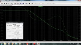
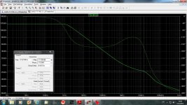
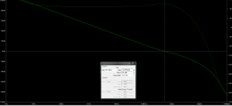
First plot below is phase margin 180-130=50degree
Second plot below is gain margin 17dB
dado
Attachments
No, phase margin at 0dB you see from OLG diagram not CLG.
dado
dadod, you should look at the phase margin at the 0dB cross over point on the LOOP GAIN PLOT and not on the OLG plot or CLG plot. This is quite an important point.
As to your question ''where should the TMC resistor be - before or after the Vi probe' my view is it should be AFTER the Vi probe. Why? because to characterize the loop gain, you need to need to excite the loop (that's what the Vi generator does) inside the feedback path. Only this way can you see what the TMC comp network, or any other comp network is doing.
BTW, I am using the Michael Tian, V. Visvanathan, Jeffrey Hantgan, and Kenneth Kundert, "Striving for Small-Signal Stability", IEEE Circuits and Devices Magazine, vol. 17, no. 1, pp. 31-41, January 2001
methodology which is given as an example in Loopgain2 in the Examples section of LTSpice. I have not had any problems. I have not tried the Middlebrook method.
dadod, you should look at the phase margin at the 0dB cross over point on the LOOP GAIN PLOT and not on the OLG plot or CLG plot. This is quite an important point.
You look for the gain margin as well on the loop gain plot? As Bob Cordell wrote?
dadod, you should look at the phase margin at the 0dB cross over point on the LOOP GAIN PLOT and not on the OLG plot or CLG plot. This is quite an important point.
As to your question ''where should the TMC resistor be - before or after the Vi probe' my view is it should be AFTER the Vi probe. Why? because to characterize the loop gain, you need to need to excite the loop (that's what the Vi generator does) inside the feedback path. Only this way can you see what the TMC comp network, or any other comp network is doing.
BTW, I am using the Michael Tian, V. Visvanathan, Jeffrey Hantgan, and Kenneth Kundert, "Striving for Small-Signal Stability", IEEE Circuits and Devices Magazine, vol. 17, no. 1, pp. 31-41, January 2001
methodology which is given as an example in Loopgain2 in the Examples section of LTSpice. I have not had any problems. I have not tried the Middlebrook method.
Bonsai, It looks that what I called OLG is actually Loop Gain, is't it??
I get that plot by inserting Middlbrook probe as in Loopgain(Examples) but not before load, but in to feedback part only. Is that all right?
dado
Bonsai, It looks that what I called OLG is actually Loop Gain, is't it??
I get that plot by inserting Middlbrook probe as in Loopgain(Examples) but not before load, but in to feedback part only. Is that all right?
dado
What you get is not loop gain.
What you get is not loop gain.
Really!
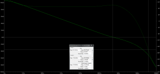
1. Loop gain plotting method as per Cordell.
2. LG from my own amplifier.
LG shows 78 degrees phase margin and a whopping 50 db gain margin.
This should be correct, yes?
EDIT : Wrote to Bob with a few questions about his way of doing it in the book. Hope he replies and is able to clear up a few things.
2. LG from my own amplifier.
LG shows 78 degrees phase margin and a whopping 50 db gain margin.
This should be correct, yes?
EDIT : Wrote to Bob with a few questions about his way of doing it in the book. Hope he replies and is able to clear up a few things.
Attachments

Neutrality, you have plotted the open loop gain and not the loop gain. You cannot adequately gauge amplifier stability from OLG plots like this. To understand or predict amplifier stability (phase margin, gain margin, impulse response etc) you need to look at the loop gain.
OLG = break the feedback loop and plot the gain without feedback. Useful for assessing the total forward gain of the amplifier. This is what you have done above.
CLG = closed loop gain. Input to output gain with feedback applied to the amplifier
Loop Gain = the open loop gain minus the closed loop gain. Because of the gain and phase redo SE over frequency, you generally should not assume you can just subtract the CLG from the OLG. And this is particularly so if you employ advanced comp techniques like TMC or ETMC.
Last edited:
Neutrality, you have plotted the open loop gain and not the loop gain. You cannot adequately ***** amplifier stability from OLG plots like this.
OLG = break the feedback loop and plot the gain without feedback. Useful for assessing the total forward gain of the amplifier
CLG = closed loop gain. Input to output gain with feedback applied to the amplifier
Loop Gain = the open loop gain minus the closed loop gain.
Well, the method shown is what Cordell described in his book on how to plot Loop gain directly.
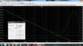
Besides, look at the method for LG plotting and the plot itself again, you reach 0 dB gain at around 500 kHz, that does not look like the plot is showing OLG and on top of that, you have only around 27.28 dB gain at 20 kHz, if this was OLG my amp would have very high THD-20. However, THD-20, 60 Watt, 8 Ohm load shows THD of 0.000674%. If the plot I posted really was OLG you would not se such low THD-20 figures.
Last edited:
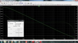
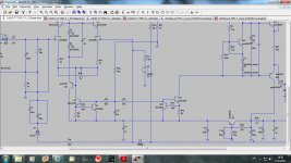
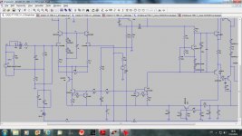
I followed instruction how to measure Loop Gain(negative feedback loop gai) from Cordell's book(page 416) and here is result.
I thing that this method is good for CMC but not TMC. I tried to move inductor to include TMC resistor in to measuring but result is strange.
dado
I thing that this method is good for CMC but not TMC. I tried to move inductor to include TMC resistor in to measuring but result is strange.
dado
Attachments
I followed instruction how to measure Loop Gain(negative feedback loop gai) from Cordell's book(page 416) and here is result.
I thing that this method is good for CMC but not TMC. I tried to move inductor to include TMC resistor in to measuring but result is strange.
dado
I just put the TMC resistor on the amplifier output side and not the NFB point side. Then I plottet the amp output. My LG plot seems ok that way and it matches what he wrote about the 0 dB point. When I compare his way of inferring OLG and his way of plotting LG, the gain crossover from the OLG plot and the point where the LG reaches 0 dB matches more or less exactly, both being around 500 kHz. This is how it is supposed to be.
In my view that more or less validates the 2 methods on plotting OLG and LG.
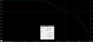
Compare these 2.
OLG and LG.
OLG gain crossover and LG 0 dB point match more or less.
The difference being around 10 kHz, due to measurements inaccuracies and the fact that the plotting methods for both OLG and LG arent 100% accurate, they are just very close approximations.
OLG and LG.
OLG gain crossover and LG 0 dB point match more or less.
The difference being around 10 kHz, due to measurements inaccuracies and the fact that the plotting methods for both OLG and LG arent 100% accurate, they are just very close approximations.
Attachments
Last edited:
- Status
- This old topic is closed. If you want to reopen this topic, contact a moderator using the "Report Post" button.
- Home
- Amplifiers
- Solid State
- How to simulate an OLG of the TMC amp