Hi mcd99uk and thank you very much for your help,
The fact of this amplifier being able of driving only 10 nF without stability issues is bad?
I Don't know if adding a small capacitor in parallel with vas resistor it's a good idea, do you use it?
About stability with the supply indutances, do you think is acceptable?
I will not test now the VI limiter, because now I'm more concerned about stability, but thank you for advices.
I will keep the TMC compensation scheme the same, I don't want to change it.
Best regards
Daniel
Last edited:
Yes, I use this capacitor in parallel with the VAS resistor. It's like free stability.
For now, yes, your supply inductance stability is ok. It's something you'll have to experiment with when you build for real.
Your amp needs to be able to do better than 10pF IMO. Try adding a small resistance in series with the test cap. Try 0.1R. In my new design I can run any capacitance I want with 0.1R in series. you have adequate PM/GM so there may be some other factor involved.
There is much discussion about this testing method. Some say its pointless due to the output inductor. Personally, I would like a little more than 10nF. As I said I have an amp that can drive 68nF. It can drive the test speakers without the output inductor over a wide range of outputs and frequencies without oscillation. Try adding the 0.1R and see how much you can drive then.
Hi mcd99uk,
Thank you once more,
Do you think that the capacitor in parallel with the VAS resistor could help?
I'm thinking in using 1-10pF, what is the value you used in your amp?
I can't simulate the circuit now, I will do it this night and then I will post the results with the vas cap, and the 0.1 ohm resistor in series with the test capacitor.
Best regards,
Daniel
Hi everyone,
Thank you for your great help mcd99uk")
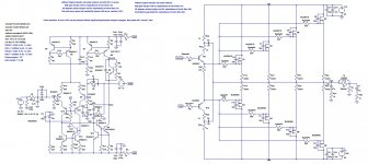
I've made the tests using the 0.1 ohm resistor in series with the capacitor, and now I can use any capacitor value, and phase shift arround the loop never reaches 180º, but with values of more than 27nF the phase shift is of less than 45º, and with 100-120nF could be as small as 6-10º, but inversion never occurs.
I've also added the bypass capacitor, that raises the gain of the VAS at high frequencies f>100MHz, by bypassing the vas resistor when the capacitor's impedance is very low, and I've set it's value to 1.5 nF what do you think?
The amp is still functional and with this improvement I've gained one more degree of PM and I've 16 dB of GM
PS: Stability while driving capacitive loads is for 45 degrees/6dB of phase margin?
Or it's ok if phase shift never reaches 180º arround the loop (PM > 0).
Best regards,
Daniel
Thank you for your great help mcd99uk
I've made the tests using the 0.1 ohm resistor in series with the capacitor, and now I can use any capacitor value, and phase shift arround the loop never reaches 180º, but with values of more than 27nF the phase shift is of less than 45º, and with 100-120nF could be as small as 6-10º, but inversion never occurs.
I've also added the bypass capacitor, that raises the gain of the VAS at high frequencies f>100MHz, by bypassing the vas resistor when the capacitor's impedance is very low, and I've set it's value to 1.5 nF what do you think?
The amp is still functional and with this improvement I've gained one more degree of PM and I've 16 dB of GM
PS: Stability while driving capacitive loads is for 45 degrees/6dB of phase margin?
Or it's ok if phase shift never reaches 180º arround the loop (PM > 0).
Best regards,
Daniel
Attachments
Sounds all good to me. Now maybe turn you attention to the SOA protection. Then if you are planning a PCB it may be a good idea to model the parasitic inductances and resistances of the traces.
One other point to note is that each MOSFET needs its own decoupling caps (electrolytic and film). When using that combination its a good idea to have an RC snubber on each rail to damp resonances.
Also, do you really need a vbe multiplier with Laterals? A simple resistor would do the same job.
One other point to note is that each MOSFET needs its own decoupling caps (electrolytic and film). When using that combination its a good idea to have an RC snubber on each rail to damp resonances.
Also, do you really need a vbe multiplier with Laterals? A simple resistor would do the same job.
Hi everyone,
Thank you very much mcd99uk for the big help you're giving me,
I'm thinking about incorporating the circuit (figure 41) of Michael Kiwanuka's papers, but I don't know how to calculate the SOA chart(s) to adjust the values, can you help me here? Please.
I will start designing the PCB layout only when I've the VI limiter circuit well defined, I'm also thinking about using an output relay that will be used for DC protection and for startup pop prevention, It's better to place the relay before or after the output inductor?
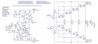
I've added the decoupling caps, but I don't know how to incorporate the RC snubber, are you talking about something similar to the RC filter present at the IPS/VAS supplies? If so what is the best value for the resistor? If it's not the same filter, can you give me an example?
I've replaced the vbe multiplier for a simple resistor with a capacitor in parallel as you suggested, and it's the same because MOSFETs (especially laterals don't need thermal tracking), in Texas Instruments application notes and in ALFET application notes it's said that a resistor can be used for lateral MOSFETs.
PS: What I should use for thermal shutdown, I'm thinking in using a comparator with hysteresis, with a common voltage divider in the inverting input, and a thermistor (mounted in the heatsink) voltage divider in the noniverting input, and then when the temperature reaches a certain threshold two supply relays are open shuting down all the amplifier, when the temperature lowers, the amplifier is reactivated, the supply relays are closed. This is a good idea? I should also actuate the output relay in this case to prevent strange sounds when the thermal shutdown is activated and deactivated?
Best regards,
Daniel
Thank you very much mcd99uk for the big help you're giving me,
I'm thinking about incorporating the circuit (figure 41) of Michael Kiwanuka's papers, but I don't know how to calculate the SOA chart(s) to adjust the values, can you help me here? Please.
I will start designing the PCB layout only when I've the VI limiter circuit well defined, I'm also thinking about using an output relay that will be used for DC protection and for startup pop prevention, It's better to place the relay before or after the output inductor?
I've added the decoupling caps, but I don't know how to incorporate the RC snubber, are you talking about something similar to the RC filter present at the IPS/VAS supplies? If so what is the best value for the resistor? If it's not the same filter, can you give me an example?
I've replaced the vbe multiplier for a simple resistor with a capacitor in parallel as you suggested, and it's the same because MOSFETs (especially laterals don't need thermal tracking), in Texas Instruments application notes and in ALFET application notes it's said that a resistor can be used for lateral MOSFETs.
PS: What I should use for thermal shutdown, I'm thinking in using a comparator with hysteresis, with a common voltage divider in the inverting input, and a thermistor (mounted in the heatsink) voltage divider in the noniverting input, and then when the temperature reaches a certain threshold two supply relays are open shuting down all the amplifier, when the temperature lowers, the amplifier is reactivated, the supply relays are closed. This is a good idea? I should also actuate the output relay in this case to prevent strange sounds when the thermal shutdown is activated and deactivated?
Best regards,
Daniel
Attachments
Danny,
Now you've caught up with me... I'm looking at ways for amp protection for my new project.
Have you considered using BC5x0c devices for Q4, 7, 13 and 14? These are transistors that experience low vce and the BC5x0c devices work better here.
Now to protection. I have been considering the idea of using solid state relays on the power rails of the amp. These have the advantage of being more reliable, never wearing out and always being able to disconnect regardless of current being drawn. All you need to do then is monitor current draw on the rails and just disconnect power. Same for DC protection. This is one way to get around being limited as to how small you can make the MOSFET source resistors.
Although, currently wondering whether this is going to provide a fast enough shutdown for DC protection.
Solid State Relay with PCB Layout
If going for standard over current protection I think only a single slope SOA limiter is required. All you need it for is to stop the peak current being drawn being too great. The laterals are good at self protecting as long as they have a chance to warm up hence limiting the current. In my working amp the current limit is set so that the devices never go beyond their DC capabilities and the fuses are set to the same. maybe not the most efficient system but should at least mean the amp will not be destroyed.
Your idea for thermal shutdown sounds feasible. A simple way could be to have thermal trips that open a latching relay which supplies the transformer with mains.
Here's some reading on enhanced VAS + 3 transistor VAS.
http://www.diyaudio.com/forums/solid-state/171159-bob-cordells-power-amplifier-book-324.html#post3508549
Interested in your ideas and thoughts on this.
Paul
Now you've caught up with me...
I'm looking at ways for amp protection for my new project.Have you considered using BC5x0c devices for Q4, 7, 13 and 14? These are transistors that experience low vce and the BC5x0c devices work better here.
Now to protection. I have been considering the idea of using solid state relays on the power rails of the amp. These have the advantage of being more reliable, never wearing out and always being able to disconnect regardless of current being drawn. All you need to do then is monitor current draw on the rails and just disconnect power. Same for DC protection. This is one way to get around being limited as to how small you can make the MOSFET source resistors.
Although, currently wondering whether this is going to provide a fast enough shutdown for DC protection.
Solid State Relay with PCB Layout
If going for standard over current protection I think only a single slope SOA limiter is required. All you need it for is to stop the peak current being drawn being too great. The laterals are good at self protecting as long as they have a chance to warm up hence limiting the current. In my working amp the current limit is set so that the devices never go beyond their DC capabilities and the fuses are set to the same. maybe not the most efficient system but should at least mean the amp will not be destroyed.
Your idea for thermal shutdown sounds feasible. A simple way could be to have thermal trips that open a latching relay which supplies the transformer with mains.
Here's some reading on enhanced VAS + 3 transistor VAS.
http://www.diyaudio.com/forums/solid-state/171159-bob-cordells-power-amplifier-book-324.html#post3508549
Interested in your ideas and thoughts on this.
Paul
How about the protection method that Pioneer used for years.
Attachments
Check out this amp that is at layout review, might be of help to you if/when you get to this stage.
http://www.diyaudio.com/forums/solid-state/243481-200w-mosfet-cfa-amp-18.html#post3677156
Cheers
Rick
http://www.diyaudio.com/forums/solid-state/243481-200w-mosfet-cfa-amp-18.html#post3677156
Cheers
Rick
Hi everyone,
Thank you mcd99uk and rsavas for your help,
Yes, I've considered replacing Q4, 7, 13 and 14, but it appears that if both transistors are not from the same model some nonlinearities are caused and the distortion suffers a little increase.
Solid state relays = Very good idea
They don't wear out like magnetic relays, and they don't do any clicking noise.
What single slope VI limiter do you recommend me to use, if you have the Michael Kiwanuka's papers can you please, give me the information about the page and figure, please?
The thermal protection can be done also with solid state relays, like the output relay?
This relays introduces a great distortion?
I've looked at Michael Kiwanuka and Bob Cordell discussion about beta enhanced VAS and cascoded beta enhanced VAS, I've tested Michael Kiwanuka's circuit and there's a great peaking there, but, I've removed the cascode and the peaking was there, I've removed the EF and I've kept only one transistor in the VAS and peaking is still there, then I've removed the VAS(TIS) and IPS(TCS) degeneration resistors to improve voltage gain, but the peaking remains. I've changed the transistors to 2Nxxxx pair (with the cascoded beta enhanced VAS) and I've no peaking in open loop gain and in closed loop gain, that's weird, why this happens, lower internal capacitances?
Many commercial amps and audio ICs uses beta enhanced VAS with emitter degeneration, it's also a fact that STK350 series uses a cascoded VAS.
Do you use cascoded VAS or beta enhanced VAS?
PS: I'm sorry but VAS is not the most correct name, this stage should be called transimpedance stage, but I'm more used to this term "VAS". I'm sorry.
Best regards,
Daniel
Last edited:
Hi Danny,
My thoughts on you points... Please remember I'm only a beginner like you. Learning loads all the time.
------------------------------------------------------------------------
The thing about LTSpice is that, IIRC, it does not model quasi saturation. so using the 2N devices instead of the BC devices in reality will likely be inferior.
All relays introduce distortion. Pick your poison. I'm going solid state as its cheaper and more reliable. These solid state relays can be used wherever a normal relay can be used. The only complication is the + rail. This will need either a floating supply to allow for enough Vgs or a photovoltaic mosfet driver.
For SOA protection for Laterals I don't see any need for anything more advanced than fig. 1 in mike k's paper. Laterals are robust anyway. They just need their peak current draw limiting. Some one will probably correct me on this
Have you looked at the PM for each VAS + miller loop? Maybe you should post you findings in the Bob Cordell thread. That way you'll get the attention of the Guru's of the site and will probably learn loads.
In the working amp I use an enhanced VAS. I'm still debating in my head whether the cascode VAS gives enough benefits for the added complexity. The difference in THD is not enough to justify all the extra components. In the enhanced VAS vs single transistor VAS contest there is only one winner by a long way and that's the enhanced VAS. In the new design I'm considering the cascode but definitely not certain I'll use it. The goal for the new design is to use cheap parts and mainly surface mount.
Don't worry about calling a VAS a VAS and not a TIS. It makes no difference to most people.
PS what happened to HEC output stage?
Hi everyone,
Can anyone help me with the single slope VI limiter?
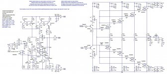
I'm testing the circuit of page 330 (figure 15.14) of Bob Cordell's book, but this circuit seems unstable. I'm thinking in using circuit of figure 23 of Michael Kiwanuka's SOA document. The problem is that I don't know how to calculate the component values, it's better to incorporate base to output capacitors in Michael Kiwanuka's circuit, if so, what are the best values to use?
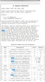
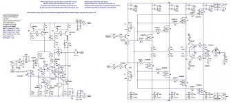
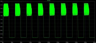
Attached are Michael Kiwanuka's protection circuits document, my circuit incorporating the single slope VI limiter of Bob Cordell's book,the components' models and the simulation graph for output shorted to ground situation, with probes placed in the source resistors, as you can see the protection for a 20kHz sinewave is unstable, with large peaks of Id current.
Thank you very much for your attention.
Best regards,
Daniel
Can anyone help me with the single slope VI limiter?
I'm testing the circuit of page 330 (figure 15.14) of Bob Cordell's book, but this circuit seems unstable. I'm thinking in using circuit of figure 23 of Michael Kiwanuka's SOA document. The problem is that I don't know how to calculate the component values, it's better to incorporate base to output capacitors in Michael Kiwanuka's circuit, if so, what are the best values to use?
Attached are Michael Kiwanuka's protection circuits document, my circuit incorporating the single slope VI limiter of Bob Cordell's book,the components' models and the simulation graph for output shorted to ground situation, with probes placed in the source resistors, as you can see the protection for a 20kHz sinewave is unstable, with large peaks of Id current.
Thank you very much for your attention.
Best regards,
Daniel
Attachments

The thing about LTSpice is that, IIRC, it does not model quasi saturation.
Here is some of the output you get when you search the LTSPICE Help file for the string "Quasi"
Attachments
Hi everyone,
Thank you very much mcd99uk for your great help,
I prefer also the solid state relays (are you looking to any model in specific?), but what is a floating supply? And a photovoltaic mosfet driver?
Could you help me choosing the component values for circuit of figure 1 of Michael Kiwanuka's papers? The VI limiter that I've posted in my last post is not very good
About beta enhanced VAS and beta enhanced VAS + cascode, both Bob Cordell and Randy Slone are in favour of enhanced VAS + cascode, I can have open loop without peaking for both enhanced VAS and enhanced VAS + cascode and I've a diference on THD1 of 0.0002% less. I don't know very much about VAS local stability tests, I don't know if one is more stable than the other, and if Michael Kiwanuka proved that 3 transistor VAS is unstable, I'm not questioning it's opinion. Michael Kiwanuka have used transistors with larger cpi(cbe) and cmiu(cbc) values than the transistors I'm using, and the transistors can misbehave when the frequency is close to it's fT. Transistors with larger cpi and cmiu capacitances will have problems at lower frequencies(10-100MHz), compared with transistors like 2Nxxxx. But has I've said I'm not an expert to question Michael Kiwanuka's or Bob Cordell's opinions. I feel tempted to use the beta enhanced VAS + cascode, what do you think?
On Semiconductor/Sanyo uses simple VAS + cascode in STK350 but it's not the same in my opinion.
About the HEC I don't know if I should use it, it seems interesting and it reduces the THD indeed, but it's very complicated and changes GM and PM pretty bad.
I will try to post something in Bob Cordell's book discussion
Thank you once more mcd99uk you are being very cool helping me,
Best regards,
Daniel
Last edited:
So I stand corrected about LTSpice and quasi saturation. Now the question is do the models have the capability.
The trouble with the positive rail and solid state relays is getting the gate source voltage. That's why you need a photovoltaic driver of another supply to provide this additional voltage. The photovoltaic driver is a neat solution.
Regarding the SOA protection. The voltage drop across the emitter resistors drives TP1 and TP2. Remove R1. Including R2 increases current limit. Get it working without these to start with. Also you can remove Rb, I didn't use it. The values of Cs can be used to make sure its stable during clipping and can allow for the protection to be delayed during transients. Connect the diodes Dp to the mosfet driver outputs. Values for R2 and R3 should be low, of the order 10-100R. Hope that helps, if needed when I have more time I'll run the .asc.
Regarding the cascode vas. It's your design you do what you feel is right. I get a THD increase in my design with the cascode VAS so can't justify the complexity at present.
Happy to help where I can. Only have limited knowledge though.
Hi everyone,
Thank you very much mcd99uk for your great help, is very kind of you
I will test the VI limiter that you've suggested and then I will post the results.
I'm concerned about that discussion between Michael Kiwanuka and Bob Cordell about the VAS, and now I'm afraid that my design could have some form of local instabilities.
I know that this amplifier has good gain/phase margins and closed loop/open loop gain without peakings.
But I've read in Bob Cordell's book that even with good global response you could have some form of local instability and you should probe, the main nodes of your circuit. Do you know how to do it?
I'm concerned about the enhanced VAS.
It could be locally instable like Michael Kiwanuka said?
Best regards,
Daniel
Hi everyone,
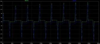
I've tested the circuit as you said mcd99uk, and the circuit is efficiently limiting the current to less than 3 A per device, but this circuit is oscillating during current limiting, and I don't know how to stop this oscillations. Can you help me?
About local stability, do you think I should do local stability tests?
The amplifier seems to have open/closed loop response with no peakings and good PM/GM, but I'm afraid of local instabilities, do you've made this kind of test to your amp?
How I can have a higher voltage supply?
I'm thinking in having only one main toroidal transformer, and a small laminated core transformer for the preamplifiers and other additional circuits. What I should add to have this higher voltage? What is a photovoltaic driver could you send a datasheet of one, or at least say one model, I really wanted to better understand those devices. Could you do the same for the solid state relays, please?
Best regards,
Daniel
Attachments
Last edited:
- Status
- This old topic is closed. If you want to reopen this topic, contact a moderator using the "Report Post" button.
- Home
- Amplifiers
- Solid State
- How to make a low distortion lateral MOSFET amplifier?