What is the typical PSU supply voltage when bias is set correctly and the bulb is not in anymore?
With both channels biased at + and - 0.62 volts thru R11 an R12, my PSU is putting out 21.8 volts into each rail.
Some caveats:
I'm using one Antec 400VA, dual 24v secondary transformer to power both channels.
I've added one additional stage to the PSU filter, making it a CRCRC; the value of my last resistor is 0.09 ohms in each rail. As an estimate, figure that to reduce my final PSU output voltage by 0.3 volts.
I also power my speaker protection, LEDs temp monitoring, clipping and VU meter drivers by the same PSU rails (figure an additional 70 mA of current draw, on each rail.
Still, figure on about 22 VDC in each rail, with healthy PSU parts, when both channels are biased properly with the RCA inputs shorted.
again
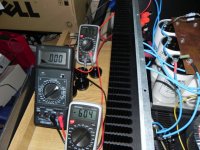
for biasing , one need just 2 voltmeters
one across any mosfet source resistor , and other between output and gnd
when voltage across one source resistor is in ballpark , and offset is near 0V - who cares what's voltage across other source resistor ?
With a variac and firing up one channel at the time, I had no problem using one multimeter. I didnt worry about the offset so much, ( in fact it was sky high at this point) until at full power and bias around .40 Then its just a matter of slowly zeroing the offset and making sure bias doent go above .59 or so....once offset zeroed see-saw the pots for final bias. With two channels at once this would have had me a little too busy, but I'm a little slow...
Russellc
To be on the safe side I decided to order 2 additional pairs of IRFP240/IRFP9240 and a third DVM.
Oh man I hope that this is it...
For those who're using cvillers V1.1 as well, can you tell me which LED and resistor (R35) types you used?
I used a 3mm blue led and a 33k 1/4 watt resistor. Nice blue glow that does'nt burn your eyes out.
To be on the safe side I decided to order 2 additional pairs of IRFP240/IRFP9240 and a third DVM.
Oh man I hope that this is it...
For those who're using cvillers V1.1 as well, can you tell me which LED and resistor (R35) types you used?
I tried a 5mm green(left) and red(right) with 33Kohm but that was too dim. A 20K was about right for me.
I used a 3mm blue led and a 33k 1/4 watt resistor. Nice blue glow that does'nt burn your eyes out.
Do you have the partnumber of the LED and where did you buy it?
Do you have the partnumber of the LED and where did you buy it?
MARL|100044|LED, 3MM, RADIAL, 15DEG, BLUE | Farnell United Kingdom
As Alazira says it depends on how bright you like them any resistor between 27k and 33k should do.
Finaly...
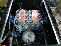
Puhhh.... I got both channels working now very well!!!
It turns out that I interchanged somehow Q5 and Q6 on my left side pcb. But luckily nothing was damaged and the amp working properly as you can see.
I also needed to add a 2.2k resistor to R3 and R4 in order to bias to 0.6V and offset it to almost Zero.
More pictures to come....
Cheers,
Mallard
Attachments
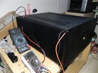
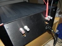
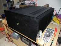
Almost done!!!
Here is my NP F5 clone
I'm currently in the process of biasing it with closed lid. It's a bit difficult because every time I open it the bias changes by itself...
Sure there is quite a bit work to do in terms of fine tuning, but step by step!
I can't wait to connect with my pre-amp and my speakers. I hope that is all the stress and the money was worth it!!!
Cheers,
Mallard
Attachments
Quote >I can't wait to connect with my pre-amp and my speakers. I hope that is all the stress and the money was worth it!!!
Nice one happy you got it going.
Swapping J fet one more thing to ad to my list of bubues.
The stress is just part of the plesure and the money You will soon find out if is worthy.
Thing to worry is about yourself.
I was wery tempted to trow a sickie just to stay home listening to mine.
(newer trown sikie before not even with a broken rib)
Guys, I am preparing for my first F5 build.
I still have some 47000uF 25V Mundorf caps in my drawer.. NP uses 25V caps in his PSU, but isn't that very marginal, given the 25V power rails?
Also when looking around... I think nobody has actually used the 25V caps... everyone has increased the voltage rating...
I still have some 47000uF 25V Mundorf caps in my drawer.. NP uses 25V caps in his PSU, but isn't that very marginal, given the 25V power rails?
Also when looking around... I think nobody has actually used the 25V caps... everyone has increased the voltage rating...

ZM, you're not going to let him challenge Papa like this...?NP uses 25V caps in his PSU, but isn't that very marginal, given the 25V power rails?
Guys, I am preparing for my first F5 build.
Great! you will love it!
I still have some 47000uF 25V Mundorf caps in my drawer.. NP uses 25V caps in his PSU, but isn't that very marginal, given the 25V power rails?
Use what you have on hand. Those are great caps and they will work very well for this project!
Also when looking around... I think nobody has actually used the 25V caps... everyone has increased the voltage rating...
DIY-people like to use overkill for many things, but the most common place is powersupply. If 25 volt caps are goos enough for Nelson's commercial projects, (Which have had a failure rate of zero once sold) then a 25v rating is certainly good enough for the project!
Also the price difference between a slightly bigger and/or higher rating is usually very small when you are only buying parts for one amp -- another reason why DIY is usually overkill.
I find a particular joy in using up the pieces and parts that I have collected over the years. If you don't use the caps in this project, what will they do? Collect dust for more time?
Anybody would help me to trace a problem?
I got one channel biased to 0,52V with zero off-set. No any problem problem there. Planning to increase to 0,6V only after a couple of days in use, per Zen Mod's instructions.
Another channel. Same practice. I cannot get bias higher than 0,06V with zero off-set. What's the problem?
I got one channel biased to 0,52V with zero off-set. No any problem problem there. Planning to increase to 0,6V only after a couple of days in use, per Zen Mod's instructions.
Another channel. Same practice. I cannot get bias higher than 0,06V with zero off-set. What's the problem?
- Home
- Amplifiers
- Pass Labs
- How to build the F5