Just out of curiosity, are they asking you to return the damaged one? (If not, it would be a great addition to your parts bin!)
No, they haven't asked for the messed up heat sink back.
I'm hoping they'll drill and tap the heat sink (before they ship it)- but that might be asking for too much.
Got a few more pictures of my build.
A drill press would realy help but does not fit in the loft and to much noise.
First off nice work.
My drill press is actually fairly quiet. At least much quieter than a hand drill.
Or more importantly, quiet enough that my wife does not know that I am using it.

Tanks again for the kind words.
Melon head Can I borow your drill press preaty please.
If you got a sense of humor I was going to ask you to borow/ swap the other bit... only joking of course no offence meant in any way
I had a look at a few drill presses and the raket was unbelivable as apparently my dremmell is far to noisy already.
Appart from jokes what make is it can you post a picture of it.
6L6
Anodising would certanly be beter only snag the bolts holding it togheter (stainless steel) may need to came off.
There is a place where I had the heath sink anodised (£30) but not realy happy with the job they did (Scratches in the wrong place but partialy my fault as should have given them a hole for the electricall connection)
This is only the mule and the build is realy fluid no drawings and such so things may change I am not realy hapy with the alluminium sheet but it was only a fiver for a 500 X 500 sheet.
Wander why is 500 x500 x320 (actualy the 320 may have to change as I have found same cheap aluminium in 500 X 300 x 3 size)
so next proper one will e similar but thiker beter stuff and welded if I can (screws and bolts weight more then the frame at present).
Last edited:
Tanks again for the kind words.
Melon head Can I borow your drill press preaty please.
If you got a sense of humor I was going to ask you to borow/ swap the other bit... only joking of course no offence meant in any way
I had a look at a few drill presses and the raket was unbelivable as apparently my dremmell is far to noisy already.
Appart from jokes what make is it can you post a picture of it.
If you were suggesting my wife is a tolerant person, then you are poorly mistaken. I can't even watch tv for more than 5 minutes before she starts complaining it is giving her a headache (I am not exagerating either).
And music, I would be lucky to get 30 seconds into the first song, before she starts complaining it is giving her a headache. Everything basically pisses my wife off.
My drill press is something like this Ryobi Power Tools :: 10" Drill Press with Exactline? Laser System but 20 years older.
Last edited:
Hi Melon Head
Same head hake problem over here...
Joga does not help then?
I had a look at that Ryoobi not bad still noise ...
I think that 20 years ago they use to make tools that where built to last now if they go to far past the under warranty period whiteout breaking some one get sacked. Stamped motors and cheap bearing= bad noise
One day I be hold enough to get a shed then things may change.
While I am here..
Merlin a Variac for first power up is a useful as a drill press when trying to get a straight hole.
There are ways around it like a light bulb and such but it definitely helps.
(Place a 100W light bulb in series with the trafo)
Besides is much smaller than a drill press and she won't notice it has been smuggled upstairs.
Same head hake problem over here...
Joga does not help then?
I had a look at that Ryoobi not bad still noise ...
I think that 20 years ago they use to make tools that where built to last now if they go to far past the under warranty period whiteout breaking some one get sacked. Stamped motors and cheap bearing= bad noise
One day I be hold enough to get a shed then things may change.While I am here..
Merlin a Variac for first power up is a useful as a drill press when trying to get a straight hole.
There are ways around it like a light bulb and such but it definitely helps.
(Place a 100W light bulb in series with the trafo)
Besides is much smaller than a drill press and she won't notice it has been smuggled upstairs.
I think that 20 years ago they use to make
When I started reading this sentence I thought you were going to say "20 years ago they used to make wives/women more pleasant and tolerant individuals"

A) Tought came to mind but cant say that or you may end up in the sin bin.
B) 20 years ago I was not building amplifiers as a hobby (maybe I should get that shed while I got a chance )
C) the cane was legal at the time was it not?
We are having a bit of a out of tipic jokes hope no one minds no offence meant just beheaving like litle spoiled kids.
Thinking about it I am not doing to bad She likes more or less the same music as me
even saw Bob Marley in the table top muntain gig and so far no frilly cinz and plants on top of the speakers.
Is a variac necessary for initially powering up the F5?
No it is not.
However, I would certainly recommend using a lightbulb in series with the PS to test the PS (without the rest of the circuit connected). If you (or someone else) are not famliar with this, there are plenty of threads you can search.
...and that the pots to set the bias are set to the minimum just in case.
While here
I am planning on F5 first and Balanced exed F5 after I gain same confidence.
So realy busy but could you suggest an easy peasy preamplifier line stage (I got a balanced line driver IC lined up but it will not do justice to Papa design) that could do both Single and balanced.
While here
I am planning on F5 first and Balanced exed F5 after I gain same confidence.
So realy busy but could you suggest an easy peasy preamplifier line stage (I got a balanced line driver IC lined up but it will not do justice to Papa design) that could do both Single and balanced.
HO HO look like few jokes killed this tread
Sorry
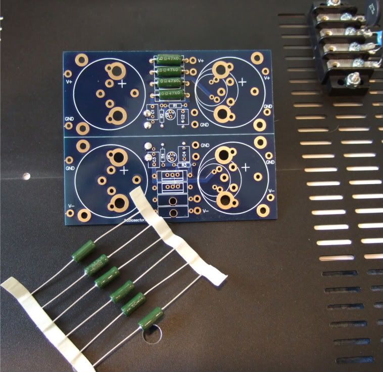
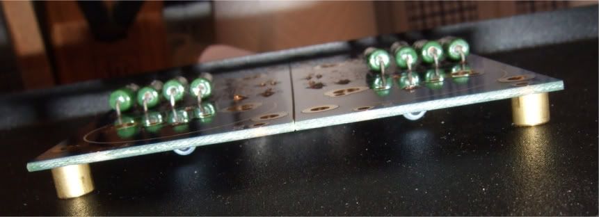
Same more pic of my build.
Capacitor bank 1 of 4 maybe 5 cooper washers sodered to PCB to improve contact and meck.
Soft start board aux pover suply
Momentary switch to power up and then thermistor switched off
2 555 as delay on timers.
Still to do 7100 speaker protection
Sorry
Same more pic of my build.
Capacitor bank 1 of 4 maybe 5 cooper washers sodered to PCB to improve contact and meck.
Soft start board aux pover suply
Momentary switch to power up and then thermistor switched off
2 555 as delay on timers.
Still to do 7100 speaker protection
Ok, finally home and in a place where I can work on the amp...
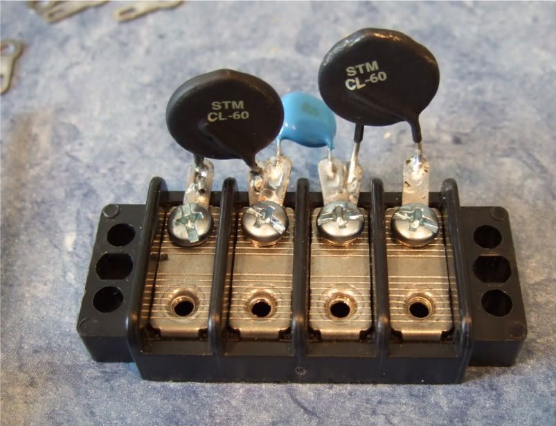
Here is the terminal block showing the thermistors and the capacitor.
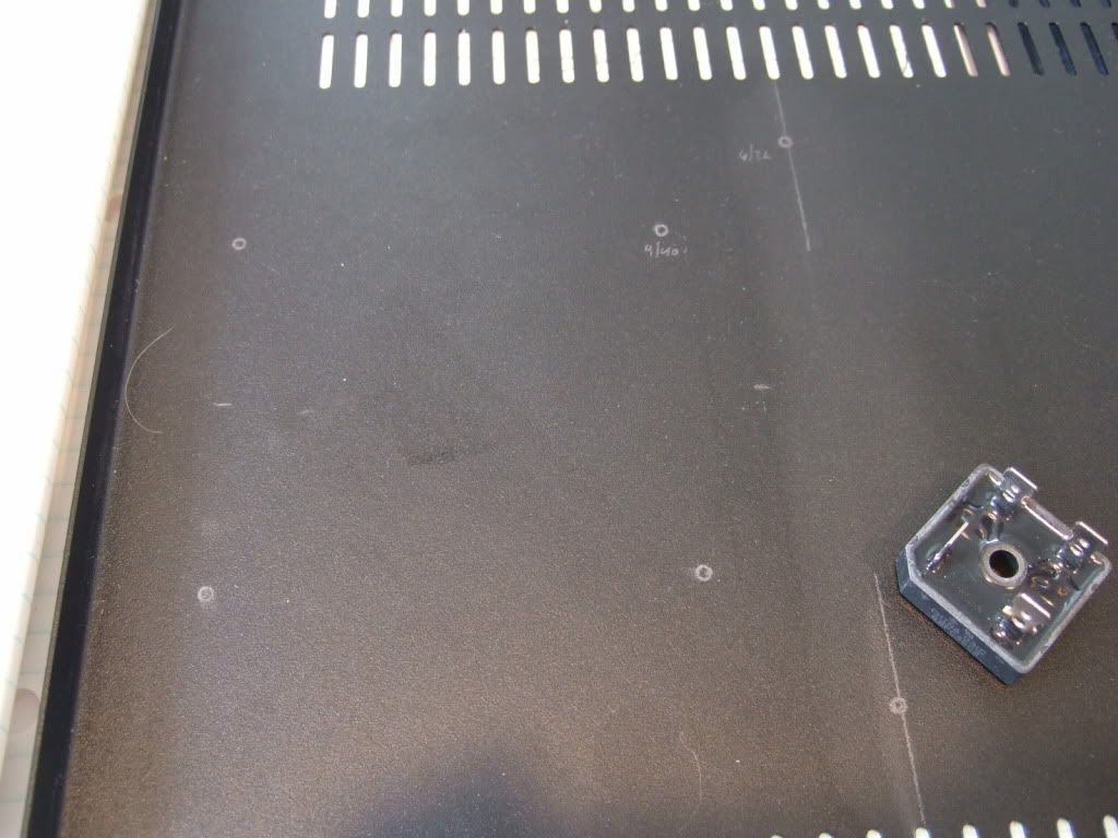
Marking the chassis bottom for the PSU board, rectifiers, and (not in photo) the transformer bolt.
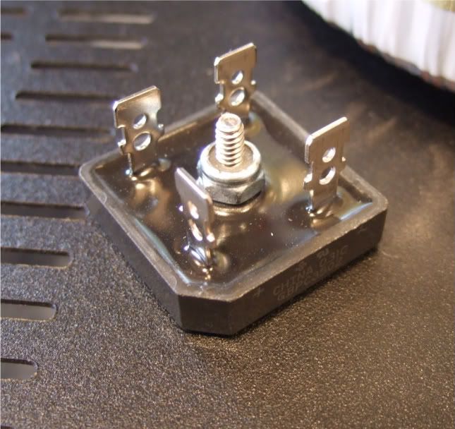
Rectifier block
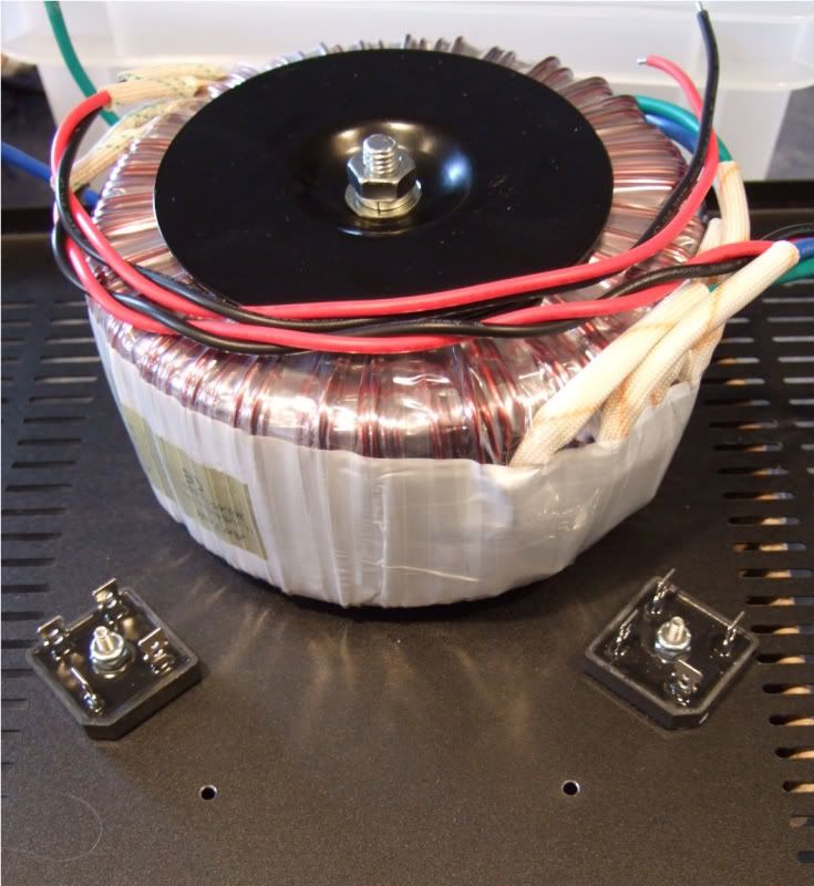
The monster Antek AN-6218
Stuffing the PSU board
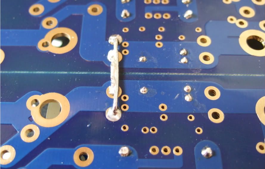
Remember to connect the grounds... Peter Daniel suggests you do it here. I am not sure if you need to have 2 jumpers like I am showing, but a good, low-impedance connection is always a good thing on a powersupply.
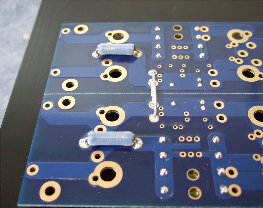
I mounted the bleeder resistors to the bottom of the board. You probably could do it on the top if you had physically smaller caps.
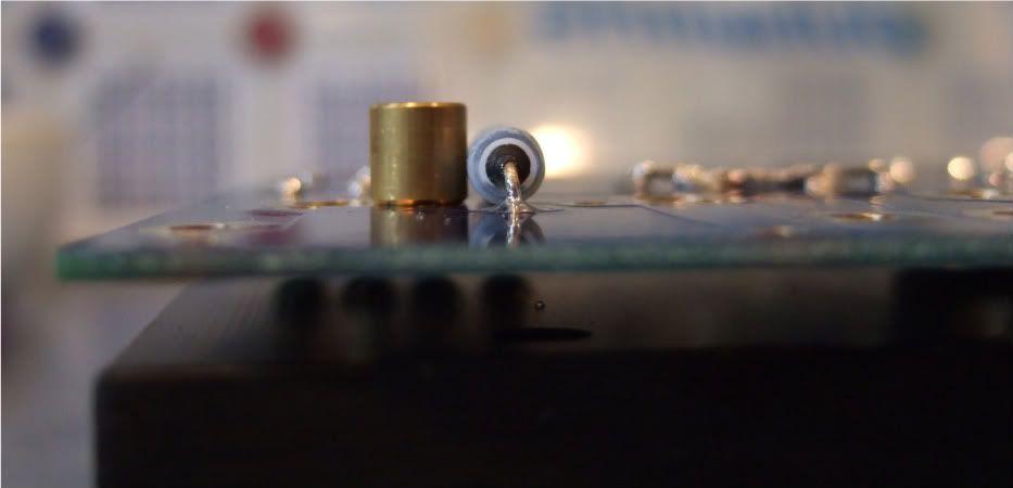
One thing that needs to be checked is if the spacers are taller than the bottom components. Looking good!
I needed to hold my camera upside-down to get the flash in a place where it could illuminate the bottom. This shows that there is plenty of room under the board.
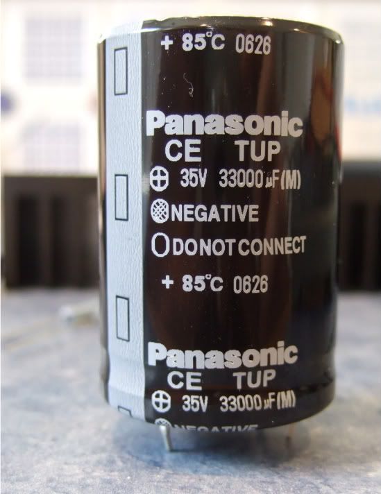
The capacitors I am using.
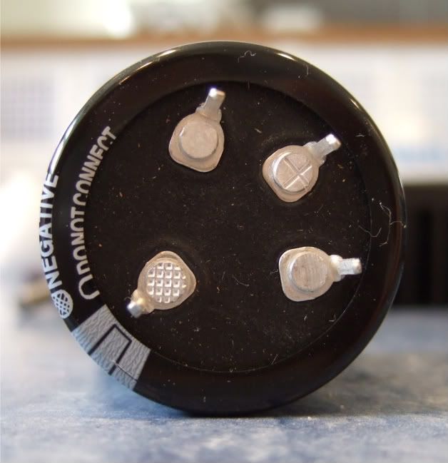
These are a 4-pin cap, and so the unmarked (and unconnected) pins need to be trimmed off.
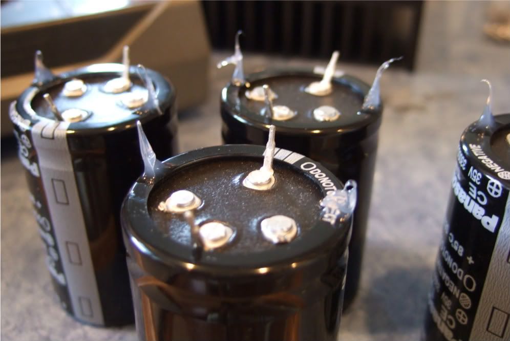
These caps are a bit big to be mounted just by two solder pins, so I am using just a small dab of silicone on the case to help stabilize and support the cans. Also note that the unused pins are now trimmed.
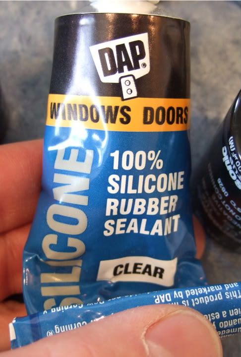
The silicone
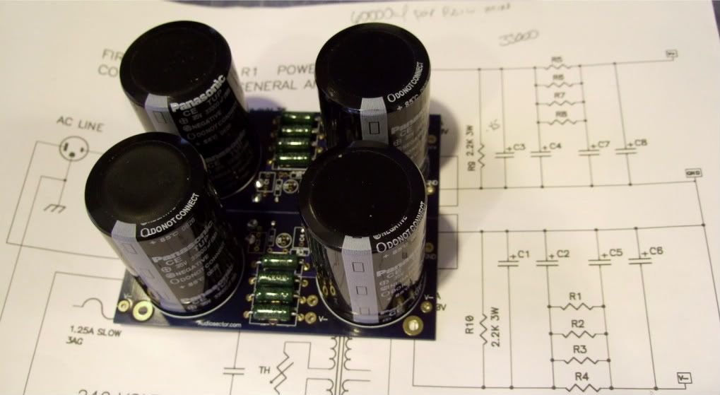
The completed (except for wires) PSU board.
Here is the terminal block showing the thermistors and the capacitor.
Marking the chassis bottom for the PSU board, rectifiers, and (not in photo) the transformer bolt.
Rectifier block
The monster Antek AN-6218
Stuffing the PSU board
Remember to connect the grounds... Peter Daniel suggests you do it here. I am not sure if you need to have 2 jumpers like I am showing, but a good, low-impedance connection is always a good thing on a powersupply.
I mounted the bleeder resistors to the bottom of the board. You probably could do it on the top if you had physically smaller caps.
One thing that needs to be checked is if the spacers are taller than the bottom components. Looking good!
I needed to hold my camera upside-down to get the flash in a place where it could illuminate the bottom. This shows that there is plenty of room under the board.
The capacitors I am using.
These are a 4-pin cap, and so the unmarked (and unconnected) pins need to be trimmed off.
These caps are a bit big to be mounted just by two solder pins, so I am using just a small dab of silicone on the case to help stabilize and support the cans. Also note that the unused pins are now trimmed.
The silicone
The completed (except for wires) PSU board.
Last edited:
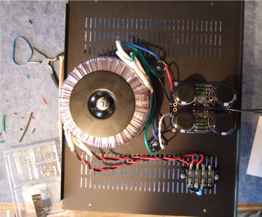
Wiring up the PSU...
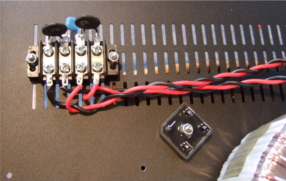
The primaries attached to the barrier strip. AC from the power inlet module will attach to the center two connections of the barrier.
Note the rectifier blocks -- the notched corner is "+" DC, it's opposite is DC "-" The other corners are AC in.
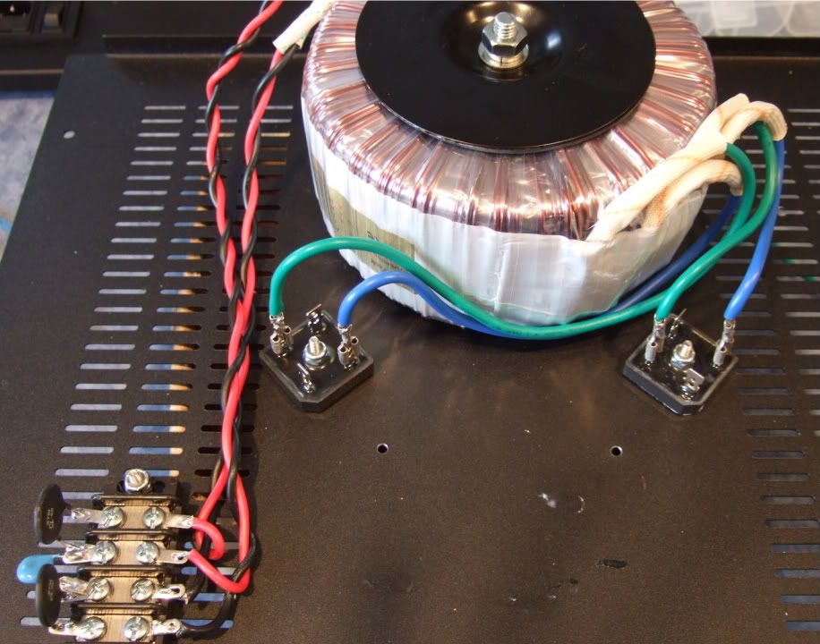
The leads of the secondaries connected to the rectifier blocks. Here you can see the AC connected to the AC in tabs of the rectifiers.
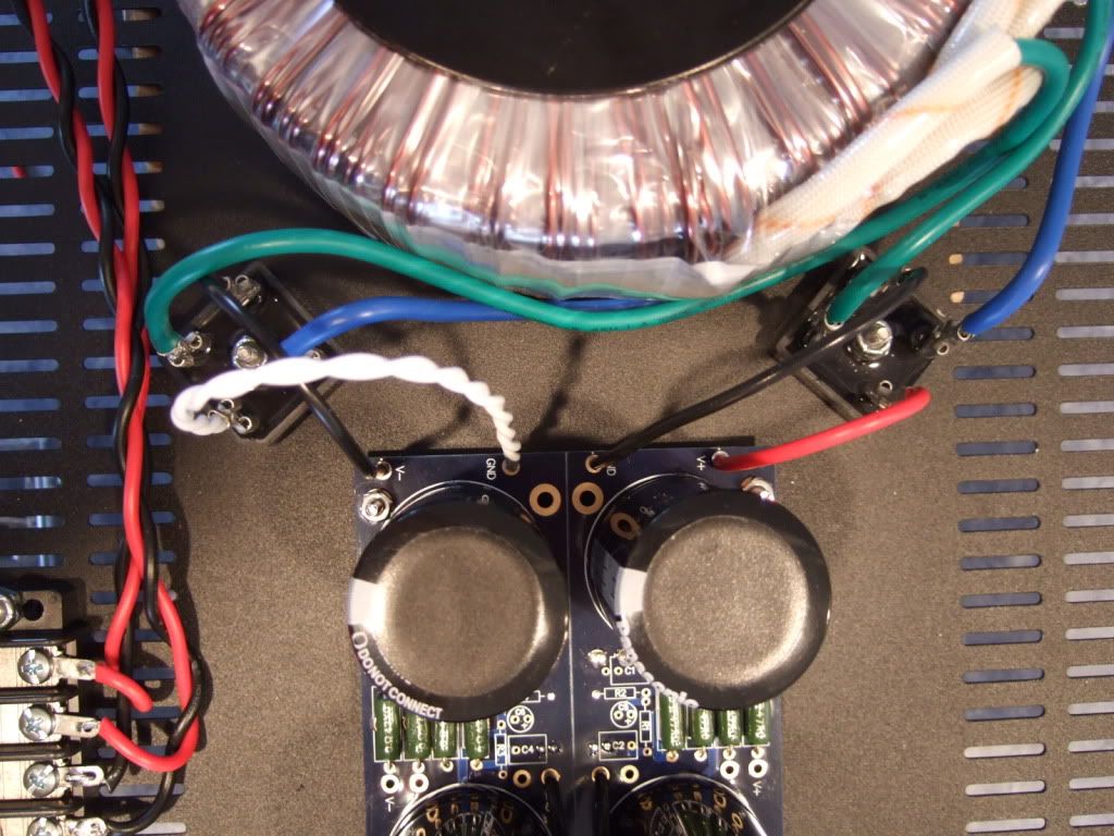
PSU board connected to the rectifiers.
The PSU completed except for AC in. This will be from the power inlet module. The black leads at the center of the PSU board will be the speaker negative connections.
The primaries attached to the barrier strip. AC from the power inlet module will attach to the center two connections of the barrier.
Note the rectifier blocks -- the notched corner is "+" DC, it's opposite is DC "-" The other corners are AC in.
The leads of the secondaries connected to the rectifier blocks. Here you can see the AC connected to the AC in tabs of the rectifiers.
PSU board connected to the rectifiers.
The PSU completed except for AC in. This will be from the power inlet module. The black leads at the center of the PSU board will be the speaker negative connections.
Last edited:
- Home
- Amplifiers
- Pass Labs
- How to build the F5