I've got a complete tube amp control board with dual high voltage detectors on board. It's on a 4" x 6" board. I still want to print the board and test fit parts to make sure everything goes before ordering boards.
Attachments

Last edited:
Hi Jeff,i see you come an expert in protection😀I've got a complete tube amp control board with dual high voltage detectors on board. It's on a 4" x 6" board. I still want to print the board and test fit parts to make sure everything goes before ordering boards.
Hi Jeff,i see you come an expert in protection😀
Hi Thimios.
I've been evolving this system for over two years now. I've got my schematics laid out so I can just cut and paste boards together now.
Next level control systems with higher power processors are coming soon.
Using lcd for condition monitoring i guess😉Hi Thimios.
I've been evolving this system for over two years now. I've got my schematics laid out so I can just cut and paste boards together now.
Next level control systems with higher power processors are coming soon.
May be a raspberry pi controlled amplifier.😀
Last edited:
I also want lcd for monitoring 🙂
If it could double up acting like a vu/power meter while not showing temperatures, bias current etc I would be in heaven.
If it could double up acting like a vu/power meter while not showing temperatures, bias current etc I would be in heaven.
I've got a complete tube amp control board with dual high voltage detectors on board. It's on a 4" x 6" board. I still want to print the board and test fit parts to make sure everything goes before ordering boards.
They look nice, I like the idea of built in fusing but most tube amps already have fusing. If you eliminated the fusing the board might get a lot smaller. For a new amp this would be awesome but retrofits will already have fusing in place.
Also need access to some of the arduino inputs to add monitoring functions.
Some may also add the LCD function as well for amp status. I also use some outputs for led connections in lieu of LCD status. I like the simple warmup led, operation led and protection led so having these extra outputs go to pins give some flexibility.
What program do you use to develop Ferber files?
The board could shrink about 7/16" if the fuses were gone. There are two PWM/digital pins that are unused. There's a 2 pin header for access to them. There are three digital pins available through the ISP port. This can double as a SPI port. There is also an I2C connector for LCD, expanders, sensors, whatever.
I do all me designing in Diptrace. It makes ugly schematics but it's pretty good software.
I do all me designing in Diptrace. It makes ugly schematics but it's pretty good software.
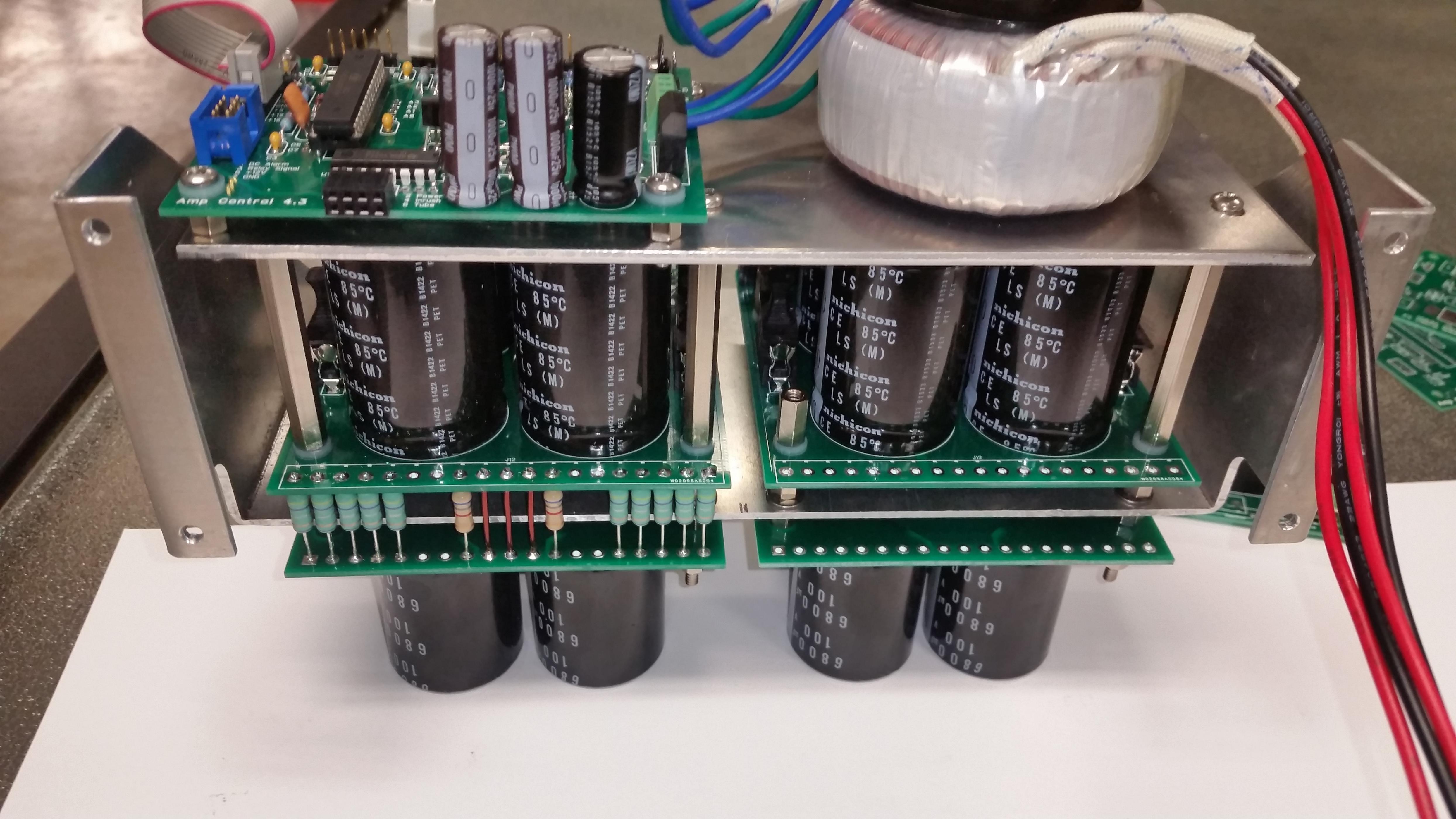
I've got a new 6 cap power supply board with rail switches running. It'll hold 35mm x 10mm snap in caps or 40mm x 22mm 4 lead caps.
This would suite my 4 lead caps, but unfortunately I need to have 6 of them per rail, not per channel. Do you think it's possible to make another board with caps only and connect it to your new board using RC resistors as you did in your previous design? Not using the rectifier section of course.
Did you follow the schematic from the previous version? I can try to design my own board as an exercise using ideas from your design.
I used pretty much the same schematic. What dimensions do you have to work with? I can put together another layout. Those supplies will be huge!
I don't have a chassis yet, but I plan to buy a 5U chassis, either 300 or 400mm deep from https://www.modushop.biz/site/index.php?route=product/category&path=66_110_111
I prefer 300mm deep because it has a one-piece heatsink which I guess is easier to work with. So using 5U chassis I could use your idea from a photo you posted here http://www.diyaudio.com/forums/atta...tury-protection-board-2016-03-07-17.48.30.jpg but with 6 caps per board not 4. Otherwise same setup.
And I don't need onboard rectifier as I already have bridges for chassis mount ...
I used pretty much the same schematic.
Do you have a BOM, please? I can't see the values from the schematic.
Thanks.
That supply looks cool ...
You better draw everything out and make sure you have room. A 300mm case fills up fast, but should work if you plan everything out first.
Here's a BOM. You can choose any output pins on the port expander. I've written the software to just turn them all off and on at the same time for simplicity. Expanders can be PCF8574 or PCF8574A They are the same devices with different addresses.
Here's a BOM. You can choose any output pins on the port expander. I've written the software to just turn them all off and on at the same time for simplicity. Expanders can be PCF8574 or PCF8574A They are the same devices with different addresses.
Attachments
The board could shrink about 7/16" if the fuses were gone. There are two PWM/digital pins that are unused. There's a 2 pin header for access to them. There are three digital pins available through the ISP port. This can double as a SPI port. There is also an I2C connector for LCD, expanders, sensors, whatever.
I do all me designing in Diptrace. It makes ugly schematics but it's pretty good software.
Is that J3 and J4?
Curious how you program the relays? Is that I2C Buss?
Last edited:
J2 is the spare digital pins. J3 is an I2C connector. The relays operate from a I2C port expander.
J2 is the spare digital pins. J3 is an I2C connector. The relays operate from a I2C port expander.
You meanJ4 is spare digital pins?
J8 is the input to optoisolator for HV monitoring, very cool!
Can J8 be configured to monitor a negative voltage in case someone wants to monitor negative grid bias? Loss of negative grid bias will cause output tube to runaway possibly burning up a tube, transformer or cathode.
This looks like the ticket, I'm ready to be the beta tester!
J4 is ISP for loading the bootloader. They are spare pins after that. J8 can be connected to any potential. That's the beauty of optoisolators.
I've got a layout done with the fusing removed. I'll see if there are any fit issues in the morning.
- Home
- Amplifiers
- Solid State
- How to build a 21st century protection board