The 3V3 version of the FTDI adapter is fine. They are 5V tolerant and the atmega328 will communicate fine at 3V3. The intermittant com issues are usually Windows/driver problems. FTDI has added killer code to their drivers to brick clone versions of their ICs but it can't tell the real ones from the fake. I've stopped using their products completely.
Thanks for the reply. Good to know that, I'll try again later and see if I can get it to communicate before splashing out on a new one.
Thanks for the reply. Good to know that, I'll try again later and see if I can get it to communicate before splashing out on a new one.
Just be aware - if it's bricked, you'll need to unbrick it first, using the "clean" driver version and methodology, that is easy to find on the internet.
Evil FTDI driver overwrites the "device ID" in the chip with "0000" - after that any driver just ignores it.
Rather embarrassingly, I had been using a Mega earlier in the day, and forgot to switch the board back to Uno. Nothing wrong with the cable or drivers. 😱Just be aware - if it's bricked, you'll need to unbrick it first, using the "clean" driver version and methodology, that is easy to find on the internet.
Evil FTDI driver overwrites the "device ID" in the chip with "0000" - after that any driver just ignores it.
That's a common mistake and easy fix! If anyone is looking for a USB/serial adapter for a project like this the CP2102 devices work very well as long as the use the DTR pin of the CP2102 to do the reset. They are very inexpensive compared to the FTDI devices and Silicon Labs is smart enough not to "brick" their own devices.
https://www.amazon.ca/USB-UART-Modu...ie=UTF8&qid=1492260486&sr=8-2&keywords=cp2102
https://www.amazon.ca/USB-UART-Modu...ie=UTF8&qid=1492260486&sr=8-2&keywords=cp2102
Rather embarrassingly, I had been using a Mega earlier in the day, and forgot to switch the board back to Uno. Nothing wrong with the cable or drivers. 😱
Ah! Cool 🙂
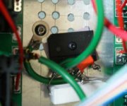
The good news is that after running the I2C scanner I finally found the addresses of my chips and got the PSU control working properly. However, I've got one DC speaker protect board working, and one not working.
The non working one does not trigger a DC condition on the processor, so I can only assume the issue is either with the mosfets or optos. From what I can see it looks like there is no voltage across the digital side of U2 (12V pin 1 -> 10V pin 4). Dinner is calling now, so I'll take another look during the week.
Many thanks, I'm getting there with this now.
Dave
The good news is that after running the I2C scanner I finally found the addresses of my chips and got the PSU control working properly. However, I've got one DC speaker protect board working, and one not working.
The non working one does not trigger a DC condition on the processor, so I can only assume the issue is either with the mosfets or optos. From what I can see it looks like there is no voltage across the digital side of U2 (12V pin 1 -> 10V pin 4). Dinner is calling now, so I'll take another look during the week.
Many thanks, I'm getting there with this now.
Dave
The mosfets won't stop the DC detection circuit from triggering a shut down. I don't remember which version you are building but here's a build guide from the latest through hole version. I'm away from civilization and using a crappy laptop so the file isn't converting to .pdf properly. Operation and testing is the same for all versions.
Attachments
The mosfets won't stop the DC detection circuit from triggering a shut down. I don't remember which version you are building but here's a build guide from the latest through hole version. I'm away from civilization and using a crappy laptop so the file isn't converting to .pdf properly. Operation and testing is the same for all versions.
Many thanks this guide is exactly what I was looking for.
Thanks for all the help! I now have everything working on both boards.
Turned out that the second speaker relay just had a bad connection on the rail from what I could tell, no other fault.
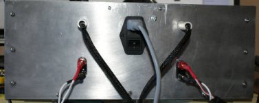
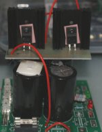
I've applied the changes to add the 1M resistors on the two lower diodes in the input bridge and also the 1uF capacitor that was added to later models. Also, I finished off the safety earth circuit as well. So far so good; I accidentally turned off a really noisy light while the system was on, connected to my test setup £30 mixer with poor isolation, didn't trip. Seems much better now.
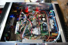
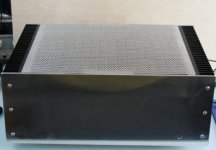
Signal to noise is still great - Ear needs to be right up to tweeter to hear any noise. Inside is also tidier now, will follow up with some photos.
Now I can get on with the exciting job of playing with my new shiny Burr-Brown 2310 volume control chip.
Turned out that the second speaker relay just had a bad connection on the rail from what I could tell, no other fault.
I've applied the changes to add the 1M resistors on the two lower diodes in the input bridge and also the 1uF capacitor that was added to later models. Also, I finished off the safety earth circuit as well. So far so good; I accidentally turned off a really noisy light while the system was on, connected to my test setup £30 mixer with poor isolation, didn't trip. Seems much better now.
Signal to noise is still great - Ear needs to be right up to tweeter to hear any noise. Inside is also tidier now, will follow up with some photos.
Now I can get on with the exciting job of playing with my new shiny Burr-Brown 2310 volume control chip.
Thanks for all the help! I now have everything working on both boards.
Turned out that the second speaker relay just had a bad connection on the rail from what I could tell, no other fault.
I've applied the changes to add the 1M resistors on the two lower diodes in the input bridge and also the 1uF capacitor that was added to later models. Also, I finished off the safety earth circuit as well. So far so good; I accidentally turned off a really noisy light while the system was on, connected to my test setup £30 mixer with poor isolation, didn't trip. Seems much better now.
Signal to noise is still great - Ear needs to be right up to tweeter to hear any noise. Inside is also tidier now, will follow up with some photos.
Now I can get on with the exciting job of playing with my new shiny Burr-Brown 2310 volume control chip.
Attached are a few final photos. There's even one showing "attic conversion" extension to fix up the diode shorting on the old PSU boards 🙂
Attachments

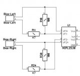
hi vzaichenko, how to calculate the resistance limiter (r10/r11) for a 500 watts amplifier +/-70 volts rails. the emitter resistor is 0.22 ohms.
thanks,
dacz
thanks,
dacz
Attachments
Last edited:
hi vzaichenko, how to calculate the resistance limiter (r10/r11) for a 500 watts amplifier +/-70 volts rails. the emitter resistor is 0.22 ohms.
thanks,
dacz
Hi Dacz,
How many output pairs do you have?
We measure the current in a single pair, so most likely you will not need to change any values (more power / more pairs = roughly the same current levels through each pair). But let's see.
Cheers,
Valery
hi,
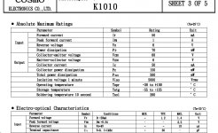
thank you for the quick reply.. my amp has 6 pairs. and my opto is k1010
OK, here's what we have, based on a simple calculation.
500W @ 8 ohm means 7.9A RMS, equal to 11.2A peak current.
Dividing it by 6 pairs, we have around 1.9A peak current per each pair.
OK, let's round it to 2A per pair, assuming some tolerance of current distribution.
2A per pair is the maximum we can reach.
Now - let's see where our current sensor is going to trigger.
Our opto triggers at around 1.4...1.5V, equivalent to 2.0...2.2V across 2 x 0.22R resistors in series, meaning roughly 4.5...5A per output pair.
Your opto is slightly more sensitive - it's going to trigger at around 1.15...1.25V, equivalent to 1.7...1.84V across 2 x 0.22R resistors in series, meaning roughly 3.9...4.2A per output pair.
So, the current, protection triggers at (4A), is roughly 2x higher than the maximum peak current through each output pair (2A). On one hand - it's a good margin in terms of false triggering, on the other hand - it must be pretty much within the SOA of your output devices, right?
That means - you can leave the resistor values as they are 🙂
If you'd like to slightly increase the current it triggers at - just slightly increase the value of R11, R24 - up to, say, 51R...56R.
Cheers,
Valery

This is actually simple and probably better to test in breadboard due to the manufacturer's tolerance in optoisolators, resistors, ect. I've found quite a bit of variance in Fairchild's optos.
Mr. jwilhelm
I've been watching this project for some time, great job. Question, any downside that you noticed to the rail switches? I can't use the bias limit on my high bias mono blocks, not enough current through the source resistor (8 pair), but I'm thinking of using it on the driver source resistors, two 15 ohms, because of the split design (one half N/P on each side of the amp). Question anyone use/using it on the driver? Thoughts?
Thanks,
MI
I've never had any issues with rail switches. They've been working great and trouble free so far.
You mean you can't use the current detection with your source resistors? Why not?
You mean you can't use the current detection with your source resistors? Why not?
Because spreading the current across 8 pairs gives about .78 vDC across both resistors @ 4 ohms 180 watts. I don't see a photocoupler below about 1.1 vDC Fv. I don't think they could make one much lower.
Last edited:
- Home
- Amplifiers
- Solid State
- How to build a 21st century protection board