Tim
Thanks for the reply.
I believe the 5687 tube is supposed to draw around 12MA. I had figured that I needed to drop about 250volts. I figured roughly 434 volts minus about 180-185 so the regulator would start. 434-254= 180volts so that would be roughly around 6.350k for resistor.
I don't know for sure what the tube(5687) will draw. I kinda wanted a working voltage at the plate of 150volts. I was thinking that a cathode voltage of about 5.2 volts would be in order.
Please feel free to correct me as needed. I need a course figuring the operational points and voltages.
Thanks in advance for the help.
Joe
Under load, it will pull down a bit from 434V. At full rated load (limited by the rectifier) it might go to 350V. Also, you realize the 272BX was designed for a 5Y3, a 6X4 is much weaker.
Is that 12 megamps per triode, or both combined? (Yeah sorry I'm pedantic about the use of symbols.. I think you mean mA.)
Let's say the supply is running at 400V. Minus 150 = 250V across the 6.35k resistor, so current is 40mA. Even with a total draw of 24mA from the 5687, the tube shouldn't go out, in fact it should have a good 16mA headroom!
Tim
Tim
Thanks for the reply. Am I to understand that the resistor value has to be dead on for this to work? How much tolerance do I have? I have tried 6.2K and it still went out.
I haven't quite figured out how to calculate the tube draw in mA.
Where am I going wrong here? I have checked and rechecked my connections and such and I haven't come across an error yet.
Also, is 150volts on the plate a good figure? Will this work well with a kathode voltage of around 5 volts?
Joe
The range for the 0D3 is 5 to 35mA. Typically you'll want to bias it so it's somewhere in the middle, say 20mA. This is pretty close to what I calculated for your case, so you should be okay.
You calculate by assuming the voltage across the resistor. This is usually accurate because the current draw from the supply is constant, whatever the load on the reg's output and because the reg'd output is always however many volts above ground. Next step is current draw. Quite simply, add total currents together, plus the 5 to 35mA the reg needs (again, middle range - 20mA - is best for most cases). Now note that you're adding currents. So if your load drops to zero, whatever current was flowing into it is now being taken up by the regulator - and likewise if the load is too strong, it sucks the current from the tube. If you have a varying load, such as screen supply in a class AB amp, you have to calculate for the current range you'll be running in. Now, divide voltage (Vsupply - Vtube) by total current to get the dropping resistor.
As long as it's always loaded in normal operation, there's nothing wrong with putting say 100mA through the dropping resistor. The total change in current just can't exceed 30mA (i.e. 70-100mA, 100-130mA, 85-115mA, etc.)
Tim
It works but only if a plate resistor is used.
Just a little update here on the 0D3 tube regulator. I was trying to use the 5687 as a load after using a 6.3K voltage dropping resistor before the 0D3. Well, it doesn't work.
What does work is not using a voltage dropping resistor and using a plate resistor. This combination is the only thing I can get to work. A 1K resistor is attached to the plate of the 5687 tube and the 0D3 comes to life. The voltage at the plate is around 130 volts. The voltage on the 0D3 side of the resistor is in the neighborhood of 150 volts.
The tube is drawing .015 per section right now. Is this in the safe zone or do I need to tone it down some?
Can anyone help shed some light on this?
Any help here would be appreciated.
Thanks
Joe

Uh.. you mean you didn't have plate resistors before???
Well Tim I got so excited with the thought of playing with a new tube(regulator) that I just plum forgot to enclude them there plate resistors.
How did you intend to get the amplified signal out of the circuit!?
By pure magic Tim.
 :
:Thanks
Simpleton said:
Pins 3 & 7 will serve as a switch to protect other tubes. Thanks.
Sch3mat1c said:Pins 3 and 7 are joined internally. This is used for cutting off power (as a removable link) in case the tube is removed and voltage soars and destroys something else in the circuit.
Tim
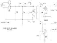
Here's the schematic for the PSU stage of my SRPP 6SN7 linestage.The 6SN7 and 5k pots work with 1K plate resistors to drop the 300v series-connected OD3 output to get 250v on the plates of the 6SN7's in the preamp section.And also to give a split-rail HT supply.Sounds VERY nice!!
Attachments
s2kov, you want to torture that tube?
the tube datasheet will tell you the maximum recommended capacitance. for the 0A3 it's like 0.1uF so a 100uF will be huge!
however, my VR105 datasheet from STC did not specify the max capacitance.
what will break a VR tube-
- reverse polarity
- overcurrent (the STC will handle up to 100mA for 10 seconds)
- dropping them?
Hi,
Plus..... People trying to stretch the envelope by a factor of thousand?
Cheers,
what will break a VR tube-
Plus..... People trying to stretch the envelope by a factor of thousand?
Cheers,
- Home
- Amplifiers
- Tubes / Valves
- How do you use a 0D3 regulator?