I would advise against that: things are more subtle than that, and even with the basic CCS, a single Bjt as cascode already shows a significant deviation.
If you test better sources, it will be completely unusable
Thanks Elvee, glad that I read that before I went up and powered up, it is simple enough to put in the jfet. Aside from the cascode transistor, you don't see any other issues with this set up?
You can use a MOSFET as the tunable perturbation signal -- this idea is original to Fred Dieckman and loosely modeled here. You lose about 4V across the MOSFET. I include some modeled results -- which you're not going to see in reality because of model limitations and the noise threshold of your measuring instrument:
Attachments


It should work, although I don't like the idea of creating a false ground (Vref) alongside the real one. If all the instruments are battery-powered, it should work transparently, otherwise earthings or leakage currents will degrade the noise floor.Thanks Elvee, glad that I read that before I went up and powered up, it is simple enough to put in the jfet. Aside from the cascode transistor, you don't see any other issues with this set up?
Thanks Elvee,
In the end I went with the positive ground system anyway, see attachment 1 for the final setup also attachment 2 shows a slightly blurry image of the setup.
I used the 2N5458 ( these are grouped for 2.5:1 spreads in parameters, this one is 4-10mA ) The first one I tested had Idss = 7.7mA and as I was planning to test a 5mA CCS, I used that device in my setup.
I decided to use the false ground / Vref for the amplifier stage only, in case of issues with the grounds of test instruments, the o/p meter is mains powered as is the signal gen and the 'scope.
In the next post I will publish my first set of results along with a diagram of the CCS tested.
Thanks jackinnj, I will look into this later.
In the end I went with the positive ground system anyway, see attachment 1 for the final setup also attachment 2 shows a slightly blurry image of the setup.
I used the 2N5458 ( these are grouped for 2.5:1 spreads in parameters, this one is 4-10mA ) The first one I tested had Idss = 7.7mA and as I was planning to test a 5mA CCS, I used that device in my setup.
I decided to use the false ground / Vref for the amplifier stage only, in case of issues with the grounds of test instruments, the o/p meter is mains powered as is the signal gen and the 'scope.
In the next post I will publish my first set of results along with a diagram of the CCS tested.
You can use a MOSFET as the tunable perturbation signal -- this idea is original to Fred Dieckman and loosely modeled here. You lose about 4V across the MOSFET. I include some modeled results -- which you're not going to see in reality because of model limitations and the noise threshold of your measuring instrument:
Thanks jackinnj, I will look into this later.
Attachments


Last edited:
Initial results when testing this 2 transistor CCS were dissapointingly low ~ 250K, I then realized that I still had the DC voltmeter connected across the CCS. The results were significantly higher, see attached image with CCS schematic and results of impedance test.
Notably there is quite a marked reduction above 3.3 KHz, I'm not sure how much of this is down to the CCS itself or limitations of the testing setup.
Notably there is quite a marked reduction above 3.3 KHz, I'm not sure how much of this is down to the CCS itself or limitations of the testing setup.
Attachments

You can use a MOSFET as the tunable perturbation signal -- this idea is original to Fred Dieckman and loosely modeled here. You lose about 4V across the MOSFET. I include some modeled results -- which you're not going to see in reality because of model limitations and the noise threshold of your measuring instrument:
I looked at your circuit and might try it to compare with my results, presumably a small signal MOSFET would be better ( lower capacitances ) in a practical circuit?
For this kind of sensitive measurement, the devil is in the detail, which is why I warned you about the DC voltmeter and other things.Initial results when testing this 2 transistor CCS were dissapointingly low ~ 250K, I then realized that I still had the DC voltmeter connected across the CCS. The results were significantly higher, see attached image with CCS schematic and results of impedance test.
Notably there is quite a marked reduction above 3.3 KHz, I'm not sure how much of this is down to the CCS itself or limitations of the testing setup.
You need to examine and question each and every minute part of your set-up, think about its impact on the measurement accuracy. That is particularly true for the output node of the CCS of course (no excessive wiring or connectors present fe.), but this doesn't mean you are allowed to neglect or overlook other aspects: there are sometimes non-dominant, completely unexpected effects coming into play, for some reason or other.
That said, your results seem to be broadly in line with the performances one could expect from a 2Q CCS
The problem with this kind of driving is not the follower: it could be a Bjt without any particular downside, but it is only really suited to 2 wire CCS's: in every other case, inaccuracies will creep in from somewhere, either the bias connection, or the place where you put the measuring shunt (which is not actually where the external loading will appear)I looked at your circuit and might try it to compare with my results, presumably a small signal MOSFET would be better ( lower capacitances ) in a practical circuit?
Initial results when testing this 2 transistor CCS were dissapointingly low ~ 250K, I then realized that I still had the DC voltmeter connected across the CCS. The results were significantly higher, see attached image with CCS schematic and results of impedance test.
Notably there is quite a marked reduction above 3.3 KHz, I'm not sure how much of this is down to the CCS itself or limitations of the testing setup.
The 3.3kHz seems a bit low - maybe you still have too mutch capacitance from your measurement system?
In simulation i get 15kHz:
Attachments


Adding 7.2 pF at the output gives 3k3 rolloff as in your measurement.
It could be the jfet, o/p capacitance is 2pF and i/p capacitance is 5pf on the d/s.
Andrew, I intend to carry out the DC testing asap, today I'm going out to enjoy the last day of glorious sunshine up here, its supposed to be raining in Scotland from tommorow and cooler, so I'd suggest you do the same if you can!
Thinking about alternatives to the jfet, there would appear to be 2 issues:
1. The measuring circuit can't load the CCS either capacitively or resistively.
2. There is a need for very high common mode rejection.(CMR)(1V:100uV = 80dB)
I got to thinking about an instrumentation amplifier, as I knew that I had an INA131 in-amp, it was a burrbrown part so not sure if you can still get it. Anyway, on the face of it this seemed like a potentially good idea, at DC the CMR is excellent at 110dB (~316 000:1) however at 10KHz it dips down to just over 60dB, which is worse than rubbish for the required application, it will be useful mind you, in measuring very high resistances at DC so it could still be put to use in that respect.
I'm going back to look at capacitance data on the other jfets I have, to see if I can find a better candidate for the existing setup.
Any other suggestions are welcome.

Another option would be a transformer, either as a stimulus driver or floating pick-up device.Any other suggestions are welcome.
With properly wound, double-screened windings, the CMR can be very high.
The technique was used in older instruments, like bridges etc.
The already good rejection can be pushed even higher using neutralization windings and caps
Have you the time to explain what this is?.................
With properly wound, double-screened windings, the CMR can be very high.
The technique was used in older instruments, like bridges etc.
The already good rejection can be pushed even higher using neutralization windings and caps
Can you post your complete measurement setup?
Maybe a jfet buffer with low input capacitance is the thing you need...
See attached, of the jfets I have at the moment the bf245 seems to be the best as regards capacitance, but only marginally better than the 2n5485 used in the setup attached.
The DC bias for the jfet is generated by the signal generator, using its DC offset control.
Another option would be a transformer, either as a stimulus driver or floating pick-up device.
With properly wound, double-screened windings, the CMR can be very high.
The technique was used in older instruments, like bridges etc.
The already good rejection can be pushed even higher using neutralization windings and caps
This sounds expensive, I am hoping to come up with something I can build from parts that I already have. However, like Andrew I'd be interested in learning more about this, if you have the time to teach us.
Gordon.
Off topic: The weather really has changed, back to late winter temperatures again, brrrr. ( for readers out with the UK. We have a ridiculous obsession here for talking about the weather, my mother for example doesn't mind so much if she misses the news, but if she misses the weather forecast she is all of axis! )
Attachments

Last edited:
Do a DC deltaV/deltaI test & measure to compare to your LF measurements.
I have come up with a setup to carry this out. ( see attached ) Arguably it is overkill but I wanted to see if I could put the ina131 instrumentation amplifier to some use, I bought it 4 or 5 years ago at a time when I was "flush with cash" along with many other interesting parts that I reckoned could make some interesting circuits!
For those unfamiliar with the ina131: INA131 Datasheet(PDF) - Burr-Brown Corporation
And for a general description of instrumentation amplifiers ( in-amps ):
Instrumentation amplifier - Wikipedia, the free encyclopedia
I haven't read through this wiki article thoroughly, but it appears to be sound.
Anyway back to my circuit, as in the ac circuit the jfet acts as the cascode transistor. R3 is the current sensing resistor, the voltage across this ( proportional to the current of course, by ohms law ) is amplified by 100 by the ina131 in-amp. The in-amp requires a stiff ( low impedance ) voltage reference at pin 5, this is provided by a 7815, 3 terminal voltage regulator at a voltage of 1/2 the 30 volt supply rail. Using a relatively hi z reference using say a potential divider made up of 2 x 1k resistors (500R source) would considerably impair the high CMR, which is important in this circuit.
With R3 = 10R, then the CCS current = vm2 ( the voltage difference between the output of the in-amp and vref ) / 100, giving a result in mA.
By measuring the CCS current I lo & I hi, at CCS test voltages of V lo& Vhi respectively, where Vhi > V lo, then R = Vhi-Vlo/Ihi-Ilo ( giving a result in k ohms, as current is in mA )
Of course R3 could be made 100R giving an output voltage of 100mV/mA that could be easily measured with a good DVM, my 4+1/2 digit meter has a 200mV range which would permit a resolution of 0.1uA, at least in theory, noise and offset errors would probably never allow this but with and expensive 6+1/2 digit DVM it could be do-able. In that case the ina131 and the 7815 and its capacitors would not be needed. R4 is not really needed either and can be replaced with a short circuit.
peufeu, posted this circuit:
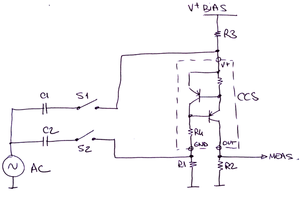
I do not entirely understand how the PSR impacts on the CCS impedance, can you explain ? I assume that omitting S2 and its respective capacitor, the rest of the circuit could be used to determine the impedance of the CCS, by dividing the ac voltage in by the current through the test resistor, R2?
Attachments

Last edited:
Thinking about alternatives to the jfet, there would appear to be 2 issues:
1. The measuring circuit can't load the CCS either capacitively or resistively.
2. There is a need for very high common mode rejection.(CMR)(1V:100uV = 80dB)
I got to thinking about an instrumentation amplifier, as I knew that I had an INA131 in-amp, it was a burrbrown part so not sure if you can still get it. Anyway, on the face of it this seemed like a potentially good idea, at DC the CMR is excellent at 110dB (~316 000:1) however at 10KHz it dips down to just over 60dB, which is worse than rubbish for the required application, it will be useful mind you, in measuring very high resistances at DC so it could still be put to use in that respect.
I'm going back to look at capacitance data on the other jfets I have, to see if I can find a better candidate for the existing setup.
Any other suggestions are welcome.
I am now reconsidering the instrumentation amplifier option, as the INA128 has over 100dB of CMR @ 10 KHz and isn't insanely expensive, £7.36 each from Mouser.
INA128P Texas Instruments | Mouser
The Mouser page includes a link to the INA128 data sheet, for those interested.
Hi,
Maybe this circuit helps you with your measurement problem.
Voltage Source V2 generates a AC voltage of 1 Volt peak.
The current through the Current Source is measured with R9.
Q4 and Q3 is a simple amplifier, the output is 3.6 mV typ. and
can be measured by a multimeter...
Greetings,
Udo
Maybe this circuit helps you with your measurement problem.
Voltage Source V2 generates a AC voltage of 1 Volt peak.
The current through the Current Source is measured with R9.
Q4 and Q3 is a simple amplifier, the output is 3.6 mV typ. and
can be measured by a multimeter...
Greetings,
Udo
Attachments

Udok, posted this circuit:
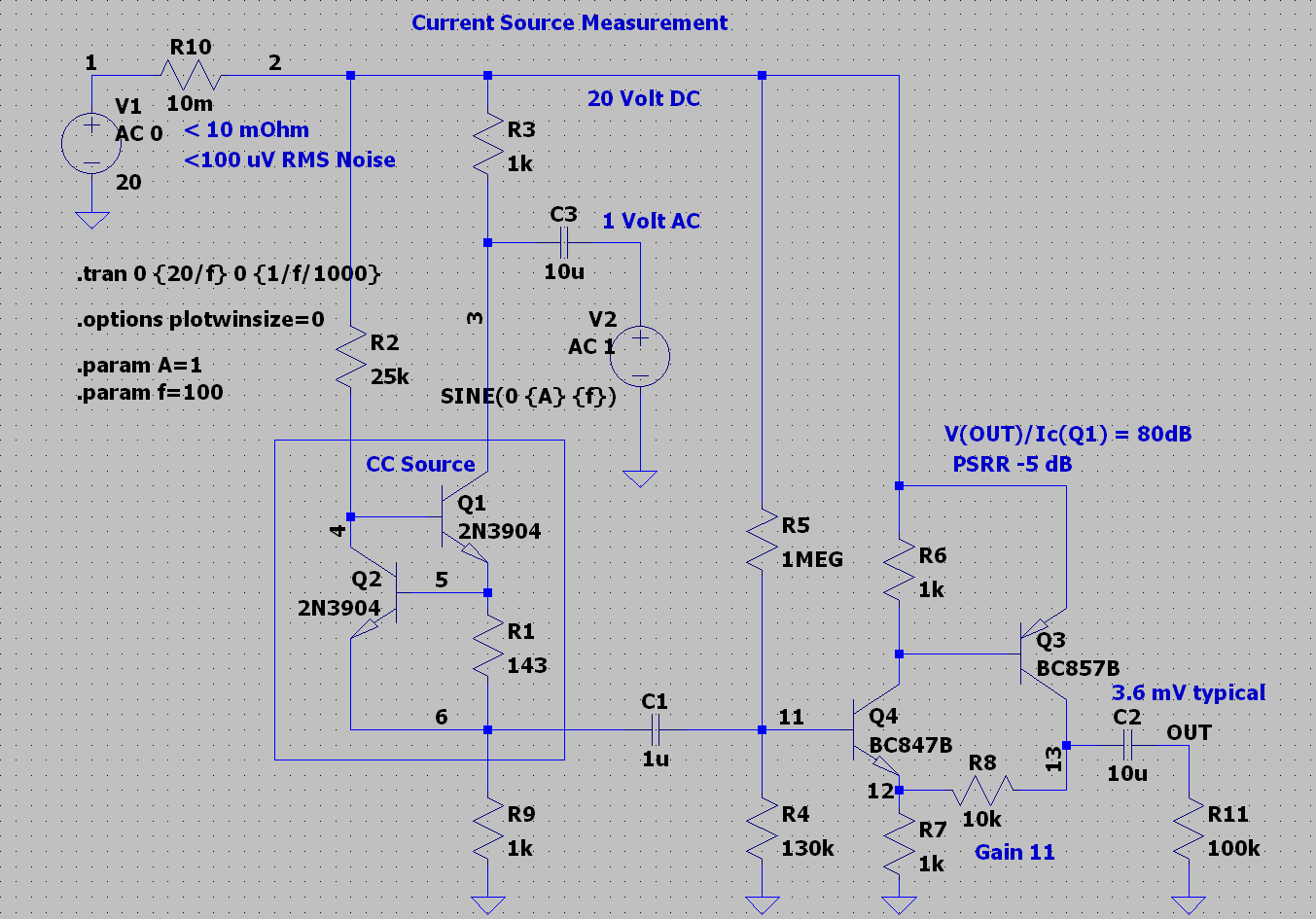
Thanks udok, I was thinking of something like this, its similar to the one posted by peufeu
The PS needs to be very clean though doesn't it?
I think it was peudeu also who suggested providing the bias for the CCS with another ccs , perhaps a simple one based on a jfet with suitable Idss, you just connect gate to source and you have a 2 terminal CCS, you would put this in place of R2.
You quote PsRR of -5dB, is this for the amplifier or the CCS?
Gordon.
- Status
- Not open for further replies.
- Home
- Amplifiers
- Solid State
- How do you calculate impedance of a current source?