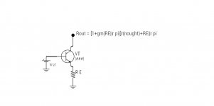
Can anyone advise on how to calculate the impedance of a bjt based current source.
What I have been able to determine thus far is that the value of r nought of the transistor is needed in order to calculate the impedance of the current source, using the hybrid pi model.
The problem is with the calculation of r nought, this is not given on data sheets, neither is Va, the early voltage which can be used to determine r nought. Someone on a physics forum suggested a graphical method of determining Va by extending the Ic / Vce curves backwards until they intersect the x axis. Is this the only way to go about finding Va and ultimately r nought and then plugging this into the hybrid pi model?
Thanks,
Gordon.
Last edited:
Member
Joined 2009
Paid Member
I might be wrong (often!) but it's the gradient of the Ic vs Vce curve at the operating point that you want, not a fictional Va. If you have the gradient then you have a pretty reasonable estimate of the collector impedance and hence a reasonable estimate when used as a single-device current source. I think ?
Last edited:
I might be wrong (often!) but it's the gradient of the Ic vs Vce curve at the operating point that you want, not a fictional Va.
Yes, the small signal parameter you want is the derivative at the operating point.
Thanks guys. ")
Yes, because Va is specified at Ic = 0, which is ludicrous!
I understand that the emitter resistor in a single device current source increases the impedance too, can anyone explain how much?
I might be wrong (often!) but it's the gradient of the Ic vs Vce curve at the operating point that you want, not a fictional Va. If you have the gradient then you have a pretty reasonable estimate of the collector impedance and hence a reasonable estimate when used as a single-device current source. I think ?
Yes, because Va is specified at Ic = 0, which is ludicrous!
I understand that the emitter resistor in a single device current source increases the impedance too, can anyone explain how much?
Member
Joined 2009
Paid Member
I would guess it helps out quite a lot - i.e. the impedance is enhanced significantly through the emitter resistor.
This emitter resistor acts as local negative feedback, it will act to reduce variations in current flow through the device by modulating the emitter potential wrt to the base. The feedback is essentially a function of the value of the emitter resistor and the transconductance of the device. You'll pick an emitter resistor that gives you a current of around 0.7V / Re. And the transconductance of a bipolar is roughly the current / 26mV, so the transconductance of the device when used as a current source will be roughly 700/26 * 1/Re = 27/Re. The current variation through Re will produce a voltage variation at the emitter which through the transconductance will act to reduce the current flow. Hmmm, sounds rather circular. For some reason it suggests that the emitter resistor will increase the collector impedance by this factor of 27 ? - have to think about that!
This emitter resistor acts as local negative feedback, it will act to reduce variations in current flow through the device by modulating the emitter potential wrt to the base. The feedback is essentially a function of the value of the emitter resistor and the transconductance of the device. You'll pick an emitter resistor that gives you a current of around 0.7V / Re. And the transconductance of a bipolar is roughly the current / 26mV, so the transconductance of the device when used as a current source will be roughly 700/26 * 1/Re = 27/Re. The current variation through Re will produce a voltage variation at the emitter which through the transconductance will act to reduce the current flow. Hmmm, sounds rather circular. For some reason it suggests that the emitter resistor will increase the collector impedance by this factor of 27 ? - have to think about that!
Last edited:
I would guess it helps out quite a lot - i.e. the impedance is enhanced significantly through the emitter resistor.
This emitter resistor acts as local negative feedback, it will act to reduce variations in current flow through the device by modulating the emitter potential wrt to the base. The feedback is essentially a function of the value of the emitter resistor and the transconductance of the device. You'll pick an emitter resistor that gives you a current of around 0.7V / Re. And the transconductance of a bipolar is roughly the current / 26mV, so the transconductance of the device when used as a current source will be roughly 700/26 * 1/Re = 27/Re. The current variation through Re will produce a voltage variation at the emitter which through the transconductance will act to reduce the current flow. Hmmm, sounds rather circular. For some reason it suggests that the emitter resistor will increase the collector impedance by this factor of 27 ? - have to think about that!
Thanks bigun,
transconductance and gm are the same, yes?
Re is 1/gm, I think.
I'm getting confused between Re, the intrinsic emitter resistance and RE the external emitter resistor.
You may well be right.
Member
Joined 2009
Paid Member
No idea !
(yes, I was using Re for the total value of intrinsic plus external, a bit naughty)
I do remember reading somewhere (Cordell I think) that the typical small signal single device current source has an effective impedance around 300k - 800k depending on emitter resistance.
(yes, I was using Re for the total value of intrinsic plus external, a bit naughty)
I do remember reading somewhere (Cordell I think) that the typical small signal single device current source has an effective impedance around 300k - 800k depending on emitter resistance.
No idea !
(yes, I was using Re for the total value of intrinsic plus external, a bit naughty)
I do remember reading somewhere (Cordell I think) that the typical small signal single device current source has an effective impedance around 300k - 800k depending on emitter resistance.
Thanks again bigun,
It was suggested elsewhere that you could build the circuit and measure it using:
∆V / ∆I, however as the variation in I will be pretty small you need a really good meter, best I can do is 4 1/2 digits, don't know if that will have sufficient resolution, might try it though and see if it falls into the range you suggested, 300~800K.
Gordon.
I think you need to refine the question in terms of applying to which circuit implementation
ie common emitter, common collector or common base.
Also interesting discussion with SY and DF96 in particular here discussing if hfe does or does not enter into results. http://www.diyaudio.com/forums/parts/221198-high-low-hfe-better-ccs.html
ie common emitter, common collector or common base.
Also interesting discussion with SY and DF96 in particular here discussing if hfe does or does not enter into results. http://www.diyaudio.com/forums/parts/221198-high-low-hfe-better-ccs.html
I might be wrong (often!) but it's the gradient of the Ic vs Vce curve at the operating point that you want, not a fictional Va. If you have the gradient then you have a pretty reasonable estimate of the collector impedance and hence a reasonable estimate when used as a single-device current source. I think ?
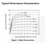
Looking at the curves for the bc547, it is essentially perfectly flat at just over 10mA, suggesting that r nought would be very high. The graph has nowhere near the resolution with which you could make a reasonable assessment of r nought.
See attached graph for reference.
Attachments
I think you need to refine the question in terms of applying to which circuit implementation
ie common emitter, common collector or common base.
Also interesting discussion with SY and DF96 in particular here discussing if hfe does or does not enter into results. http://www.diyaudio.com/forums/parts/221198-high-low-hfe-better-ccs.html
It was the common emitter implementation, see attached.
I will have a look at that other thread,
Thanks,
Gordon.
Attachments

Hawksford wasn't original but its a OK treatment of output Z increasing circuit options:
https://web.archive.org/web/2013012..._lab/malcolmspubdocs/J10 Enhanced cascode.pdf
https://web.archive.org/web/2013012..._lab/malcolmspubdocs/J10 Enhanced cascode.pdf
Thanks Sreten, the problem is there isn't any software like this that will run on an android tablet. I think its time to try and fix my laptop!
TINA-Cloud won't run on Android?
Thanks Sreten, the problem is there isn't any software like this that will run on an android tablet.
http://easyeda.com/ has schematic entry and simulation capability which should work in your browser. The sim looks rather similar to LTspice.
Member
Joined 2009
Paid Member
Looking at the curves for the bc547, it is essentially perfectly flat at just over 10mA
If the data sheet is correct it implies that this device would be a good choice for a CCS. And perhaps with such devices the effective impedance is high enough for your application that you don't much care what it is ?
It is very easy to measure the DC impedance of a CCS.
I have done that a few times.
Measuring the AC impedance is a very different ball game.
I have never done this.
A current source has two different output impedances depending on what you are interested in...
The usual one : in the simulator, power the CCS from a perfect voltage source. Put an AC voltage source as the load of the CCS. Plot v(out)/i(load), or just v(out) if you specify "AC 1" as the load. This gives you output impedance.
The other one is transimpedance, which is kind of like PSRR. You power the CCS from an AC source, and measure the output current with a suitable load, like a 0 ohm resistor or whatever. In this case the transimpedance is V(in) / i(load).
If your CCS is a two-terminal device like a JFET, both are identical.
If it is a 3-terminal CCS, like a BJT biased by a LED which is biased by a resistor to GND (the 3rd terminal), then the two are different. You can have good output impedance and low PSRR, for example, if variation of the supply voltage leaks into the CCS bias.
Measuring the last one is easy : power the CCS from a variable voltage (I use an emitter follower, cap-coupled to the soundcard output), use a resistor as load, and look at voltage variation on the load. At higher frequencies, collector capacitance dominates.
Measuring the first one is not that easy...
Fortunately simulations are very accurate for this (except at low frequency where self heating occurs).
Last edited:
- Status
- This old topic is closed. If you want to reopen this topic, contact a moderator using the "Report Post" button.
- Home
- Amplifiers
- Solid State
- How do you calculate impedance of a current source?