Mooly, thank you for your replies and the link to the nifty calculators.
Can you please shed some light on what a low pass filter would look like on the input of my AD825 circuit? Is it just the opposite of a high pass where you have a resistor in series and a capacitor to ground?
I thought placing a small cap across Rf limited the bandwidth of the op amp?
Yes, a first order low pass filter just swaps the position of R and C compared to the high pass. Again there are no hard and fast rules. I've seen values as low as 220 ohm and 220pf for an input low pass filter on chip amps (giving over 3Mhz as a -db point) right down to values giving nearer 50 or 100kHz as a cut off. Also remember that the output impedance of the volume control as seen at the wiper alters with rotation and that change in impedance modifies the filter response a little as well.
The cap across the feedback resistor reduces the loop gain of the amplifier at hf and is used to ensure stability and freedom from oscillation. The input filter places definite limits on the rise time of any signal that can actually reach the chip in the first place.
Sorry but:The cap across Rf actually increases the loop gain at hf. Nevertheless, if it's not too large, it does potentially contribute to stability by providing some phase shift, speeding up the feedback.
1) a cap across Rf decreases gain at hf .
2) an hf cutting cap in the loop does indeed provide a phase shift, but you can't assume it always increases stability.
Often it's quite the contrary, it depends on internal phase shifts caused by other elements, all phase shifts add up and may reach positive feedback at some frequency.
Some extra Bandwidth Op Amps achieve that by not being compensated for stability at unity gain or below, say, 10X gain.
Some popular chipamps too, they demand closed loop gain >20dB, that's why sometimes datasheet examples suggest, say, 20K/1K NFB resistors.
From TI LM3886 datasheet:
The LM3886 is designed to be stable when operated at a closed-loop gain of 10 or greater
Last edited:
Because I don't like caps in the signal path...especially two.
If I knew which filter was more important, I wouldn't be asking now would I??
I didn't ask what you know, I asked what you thought. I assume you have been thinking about this circuit, and that you know what your goal is.
I ALWAYS recommend that the input to every piece of audio gear has both a High Pass Filter AND a Low Pass Filter to determine the passband of the equipment.
The high pass also blocks DC and helps prevent damage.
The low pass helps to attenuate Radio Frequencies (RF) and other interference. This reduced level of HF can help the amplifier behave when not presented with very fast changing signals.
The high pass also blocks DC and helps prevent damage.
The low pass helps to attenuate Radio Frequencies (RF) and other interference. This reduced level of HF can help the amplifier behave when not presented with very fast changing signals.
A good point that I had not considered.Sorry but:
1) a cap across Rf decreases gain at hf .
2) an hf cutting cap in the loop does indeed provide a phase shift, but you can't assume it always increases stability.
Often it's quite the contrary, it depends on internal phase shifts caused by other elements, all phase shifts add up and may reach positive feedback at some frequency.
Some extra Bandwidth Op Amps achieve that by not being compensated for stability at unity gain or below, say, 10X gain.
Some popular chipamps too, they demand closed loop gain >20dB, that's why sometimes datasheet examples suggest, say, 20K/1K NFB resistors.
From TI LM3886 datasheet:
.:Sent by pneumatic tubes
I didn't ask what you know, I asked what you thought. I assume you have been thinking about this circuit, and that you know what your goal is.
Sorry, I took your question out of context. My goal is to build a linestage with a gain of 2 with a chip like the AD827.
I'm starting to believe that these filters may be necessary since I have a plasma television, which I would think emits some type of garbage that could be amplified by the op amp.
The 'in the signal path' thing's just a myth because current flows around loops, not along 'paths'. If you're really serious about avoiding caps then any decouplers you've got on the supply rails (including reservoir caps you may have after a rectifier) will have to come out because the current flows through them too.
No, I'm not that serious. The caps in the power supply and the decoupling caps on the op amp's supply pins are staying.
So are you saying that caps in series with the audio don't affect or degrade the sound?
I ALWAYS recommend that the input to every piece of audio gear has both a High Pass Filter AND a Low Pass Filter to determine the passband of the equipment.
The high pass also blocks DC and helps prevent damage.
The low pass helps to attenuate Radio Frequencies (RF) and other interference. This reduced level of HF can help the amplifier behave when not presented with very fast changing signals.
Okay, how about giving me some idea of cutoff frequencies for each?
50KHz, 100KHz or 150KHz for the low pass?
1Hz, 2Hz, or 5Hz for the high pass?
So are you saying that caps in series with the audio don't affect or degrade the sound?
Why do you introduce straw man arguments in this thread?

Are you trying to solve a real Tech problem here or just throwing balls at random to see whether somebody catches them?
Okay, how about giving me some idea of cutoff frequencies for each?
50KHz, 100KHz or 150KHz for the low pass?
1Hz, 2Hz, or 5Hz for the high pass?
Personal choice which in great part depends on program material being reproduced through this buffer.
Which by the way is not Brain Surgery
")
Just a 2X gain buffer
Do you find it so complex?
Why do you introduce straw man arguments in this thread?
Are you trying to solve a real Tech problem here or just throwing balls at random to see whether somebody catches them?
Personal choice which in great part depends on program material being reproduced through this buffer.
Which by the way is not Brain Surgery
Just a 2X gain buffer
Do you find it so complex?
"Straw man arguments" & "throwing balls at random"...you're so funny.
"Program material" for me is called music.
"Brain Surgery"...another funny comment.
Yes, I do find it so complex.
Since you seem to have all the answers, why don't you post a schematic of a "simple 2X gain buffer"??
Sarcastic and noninformative replies like yours are a waste of my time to read.
Sorry, I took your question out of context. My goal is to build a linestage with a gain of 2 with a chip like the AD827.
I'm starting to believe that these filters may be necessary since I have a plasma television, which I would think emits some type of garbage that could be amplified by the op amp.
OK, but you were asking about output offset voltage and input bias current. Several very patient people have told you how to deal with those things. So the cap to ground on the feedback network is there to reduce DC gain to unity, hence I would expect that filter would be important to you. Equally the DC blocking cap (another high-pass element) is present to isolate the volume pot from the input bias current, so I would expect that to be important to you. The input low-pass is to shunt away RF junk and protect the stability of the amp, which were not your stated goals (just best practices) so you can feel free to ignore it if you are feeling too tired. Likewise HF bypass on the feedback resistor.
The point is that this is your project and only you can decide what is important.
Okay, how about giving me some idea of cutoff frequencies for each?
50KHz, 100KHz or 150KHz for the low pass?
1Hz, 2Hz, or 5Hz for the high pass?
Those are all reasonable choices. Pick some and do the arithmetic and see what sort of R and and C values you end up with.
OK, but you were asking about output offset voltage and input bias current. Several very patient people have told you how to deal with those things. So the cap to ground on the feedback network is there to reduce DC gain to unity, hence I would expect that filter would be important to you. Equally the DC blocking cap (another high-pass element) is present to isolate the volume pot from the input bias current, so I would expect that to be important to you. The input low-pass is to shunt away RF junk and protect the stability of the amp, which were not your stated goals (just best practices) so you can feel free to ignore it if you are feeling too tired. Likewise HF bypass on the feedback resistor.
The point is that this is your project and only you can decide what is important.
You're correct in that my primary concern was DC offset at the outputs since I have encountered this before with higher Ib op amps.
Mooly stated that offset would be lower with the feedback and input shunt resistors being the same value and shared the idea of the cap to ground on the feedback network...something else I didn't know about.
So yes, I realize that it's important, too.
Then another member stated, like you just stated above, that it's good practice to have both a low and high pass filter on the input.
Up until this point, I've never used any kind of trap on the input of an op amp circuit.
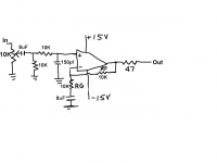
So now I'm at the point of making sure my schematic below is correct for both a low pass and high pass filter on the input.
I calculated the -3dB point of the high pass at 2Hz and the -3dB point of the low pass at 106KHz.
Does this look OK to you, or do you see things I need to change?
Do both filters go after the volume pot like I have it drawn?
Thanks...
Attachments
I don't have a breadboard or I would try that. I would have to solder it up and see what happens.
What would you use for a series resistor, 100 ohm or 1K?
Looks as though the feedback resistors are too large as well as shown in the AD827's datasheet below. They don't recommend anything over 5K.
Here's a link to the datasheet itself:
http://www.analog.com/static/imported-files/data_sheets/AD827.pdf
Attachments
So are you saying that caps in series with the audio don't affect or degrade the sound?
No - since 'sound' is perfectly subjective I'd not make a blanket statement about other people's 'sounds'. In my experience though the caps on the supply are a bigger issue for sound than coupling caps. For example I use (contrary to the consensus here) 10uF X7R 1206 ceramics to couple my DAC to my amp and don't hear any issues, but decoupling caps are a different story all together. I realize this makes me a heretic but hey that's life
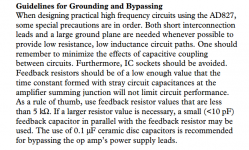
You have to remember the AD827 is designed as a wide bandwidth device and that is one reason the feedback resistors are recommended to be less than 5k. Using higher than 5k will limit ultimate bandwidth and slew rates (due to stray capacitance effects for one reason) but you also have to remember that audio applications don't come close to needing what a device like this can offer.
I would suggest that whatever you decide, that it should be backed up by real measurements to confirm stability and lack of ringing and so on.
As to the filters... why don't you try more extreme values, say 20Hz and 40kHz in a test circuit and then compare with say 2Hz and 400kHz and see whether there was any audible effect or loss to you.
In your latest circuit the + opamp input should just see 10k to ground so that it matches Rf.
The circuit in post 57 has 20k on one input and 10k on the other, so input current will generate a voltage offset. Of course, using lower value resistors will reduce this problem, but you have to be careful not to load the source too much. Is this an appropriate opamp for this application?
- Status
- This old topic is closed. If you want to reopen this topic, contact a moderator using the "Report Post" button.
- Home
- Source & Line
- Analog Line Level
- How can this work?