No, much much more than 10uF to the supply. You'd need an array of SMT ceramics (say 10uF 1206 types) between the supply pins and then beyond that a further array of electrolytics into the 33,000uF+ ballpark. What you've described doesn't sound to me to be in the least 'heroic' ")
<edit> At first blush this probably sounds totally crazy right? So I suggest convincing yourself that it makes a difference by doing it in smaller increments. Start with half a dozen of the 1206 ceramics (watch the supply volts - I suggest you run lower rails to get more capacitance from these) and see what improvements you hear.
<edit> At first blush this probably sounds totally crazy right? So I suggest convincing yourself that it makes a difference by doing it in smaller increments. Start with half a dozen of the 1206 ceramics (watch the supply volts - I suggest you run lower rails to get more capacitance from these) and see what improvements you hear.
Last edited:
Argh...SMT components...something I've never used before and try to avoid at all costs.
I'm seeing them used in a lot of circuits now. I don't know if I can solder them in place, or not.
Yeah, initially it sounds pretty crazy, but as with most things I can't really knock it until I've tried it personally.
33,000uF worth of electrolytics? I assume you mean a LOT of smaller electrolytics in parallel?
beyond that a further array of electrolytics into the 33,000uF+ ballpark.
to feed a dual Op Amp buffer which eats ... what ? .... 5 mA ?
<edit> At first blush this probably sounds totally crazy right?
Well, YOU said it , not me
33,000uF worth of electrolytics? I assume you mean a LOT of smaller electrolytics in parallel?
I use 3,300uFs so ten. Is that a lot? Paralleling smaller 'lytics gets lower ESR but I don't see much value in going smaller than 3,300uF except at higher voltages where 3,300uF is a bit bulky.
Since 50MHz video amps are being used, rather than lowering ESR at Audio frequencies which is, frankly, quite useless, we should start considering supply snubbering (like carlosfm recommends), capacitor leg inductance, the natural frequency of the transmission line formed by distributed capacitance and inductance and other important matters.
Otherwise, why bother?
Building a Gainclone chip amp with snubberized PSU.
To put it in other words: having 33000uF capacitance filtering/bypassing a seemingly small Dip8 Op Amp can give you a false sense of security, ..... because at 50MHz you might even have no filtering at all.
The original thread:
http://www.diyaudio.com/forums/chip-amps/43423-high-cap-unregulated-psu-chipamps.html
Where it says these very realistic words:
Somebody there thinks similar to abraxalito:
Otherwise, why bother?
Building a Gainclone chip amp with snubberized PSU.
To put it in other words: having 33000uF capacitance filtering/bypassing a seemingly small Dip8 Op Amp can give you a false sense of security, ..... because at 50MHz you might even have no filtering at all.
The original thread:
http://www.diyaudio.com/forums/chip-amps/43423-high-cap-unregulated-psu-chipamps.html
Where it says these very realistic words:
Lately I've been thinking...
Why the hell don't these chips like high capacitance?
Why do they sound bad?
The reason is so simple that in the end I just wanna kick myself.
Bigger caps have higher inductance, and the amp will have lower damping factor at mid/high fequencies.
The thing is: these chips are really sensitive to this.
Go higher than 1500uf per rail/chip and you start noticing that the midband and treble magic goes away.
The more capacitance you add, the worse it sounds.
Somebody there thinks similar to abraxalito:
Personally I would use 10x 1000uF instead of 1x 10000uF, connected using a sheet bus, and as close as practical to the chip supply pins.
Paralleling all those ESR's and ESL's really works in your favour, ripple current handling goes right up, and you get to choose from the ultra-low impedance types from Nichicon, Rubicon etc.
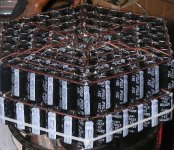
You were envisioning something more like this?
LOL...that's funny!
Yes, that's what I first envisioned.
- Status
- This old topic is closed. If you want to reopen this topic, contact a moderator using the "Report Post" button.
- Home
- Source & Line
- Analog Line Level
- How can this work?