to save you the trouble of finding them yourself.
The basics were all that I was asking for. I'm sure all that information is available on the net somewhere, but it isn't that easy to find. Feeding me bits n' pieces doesn't help.
I spent most of last night looking at LOW pass filters like you suggested, thinking I needed to pick some really high frequency like 50 kHz and design a filter to pass everything below that, not 2 Hz like Mooly suggested.
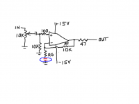
Your circuit in post #10
There are no hard and fast rules... you need to decide on the midand gain you want. Lets say you want a voltage gain of 15.
The gain is (Rf+Rg)/Rg and so you need resistors in a 14:1 ratio. i.e. if Rf were 14 ohms then Rg would be 1 ohm.
So what are suitable values. Typically we would set Rf at the 10k to 30k region. Any higher and noise contribution might start to become significant. Go lower and the opamp has to work harder to drive the feedback network and distortion rises.
So its a compromise that depends much on the opamp used.
Lets say we use a 10k. That means Rg has to be 714 ohms. We would use 680 as a nearest preferred value.
What about the cap in series with Rg. You decide the -3db point you want the amp to roll off at. Lets say 2Hz. With a 714 ohm resistor that means you need a 110uf cap. That would ensure the response was 3db down at 2Hz.
The resistor you have shown as 100k on the input needs to match Rf for minimum DC offset. This is because for bipolar opamps a steady DC bias current either flows out of or into the opamp input pin from ground. That current develops a volt drop across the 100k which causes the DC offset when the voltage at the other input pin is unequal. So to equalise them, Rf and the input bias resistor need to be the same value.
Use a FET opamp with essentially zero DC input bias current and the offset problem vanishes.
The input cap is chosen in the same way as the feedback cap. You then have two filter networks in the chain and the actual -3db point would shift from 2Hz to nearer 3Hz with the combined effect of both networks acting on the amp.
Does that help ?
Yes it does...thank you!
A few questions:
1) So if I want a gain of only 2, then I would use 10K resistors for Rf, Rg and from the input to ground, correct?
2) How did you calculate what size cap that goes in series with Rg for a -3dB point of 2Hz? Can you please share the formula?
3) Is the 100 ohm resistor still necessary on the + input for stability?
4) When calculating the input cap's value, which resistance would I use? The 10K going to gnd, the 100 ohm or the value of the volume pot?
Attachments
DC blocking capacitors on both the input and the negative feedback leg.
Gain set by the ratio of Rf : [Rg+Xc of cap]
one input filter set by cap & 10k
That's a good start.
As said earlier determine the midband gain (I like to call it passband gain).
Initially ignore all the capacitors and determine the passband gain
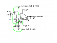
Then use F-3dB = 1 / [2PiRC] for either a high pass filter (the LF limit of the passband), or for a low pass filter (the HF limit of the passband).
The low pass filter is missing. Add one to the input.
For lowest output offset, check that the "resistances" seen by the +IN pin match the "resistances" seen by the -IN pin.
These may need a very small adjustment to compensate for input offset current inequalities.
Gain set by the ratio of Rf : [Rg+Xc of cap]
one input filter set by cap & 10k
That's a good start.
As said earlier determine the midband gain (I like to call it passband gain).
Initially ignore all the capacitors and determine the passband gain
Then use F-3dB = 1 / [2PiRC] for either a high pass filter (the LF limit of the passband), or for a low pass filter (the HF limit of the passband).
The low pass filter is missing. Add one to the input.
For lowest output offset, check that the "resistances" seen by the +IN pin match the "resistances" seen by the -IN pin.
These may need a very small adjustment to compensate for input offset current inequalities.
Last edited:
The low pass filter is missing. Add one to the input.
I'm confused now...
I thought the image in post #15 is a low pass filter, or is it a high pass? If not, what does a low pass filter look like?

Barefoot gave the right answer in the 2nd post.
Nigel is almost right. The capacitor and the impedance that follows it form a high pass filter. The corner frequency of the filter is dependent on both values. On a preamp output you have to deal with the reality that the load might be as little as 600 ohms, so fairly large capacitor values are often used, such as 10uf
So are you saying that I will need large 10uf caps on the outputs?
Yes, a capacitor followed by a resistor connection to Signal Ground/Return is a high pass filter. It cuts off the low frequency signals that you don't need in the passband.
Okay, I understand that I have a high pass filter in the circuit as I have it drawn.
What does a low pass filter look like?
So are you saying that I will need large 10uf caps on the outputs?
There are two reasons you might.
1: the load you are driving might be low. so it might be forming a low pass filter that will mess with the sound. So you use a larger capacitor to assure that the corner frequency remains very low.
2: the load you are driving might also be capacitor coupled. series capacitors halve their value. see above wrt frequency response.
I really prefer to design out the offset and DC couple my outputs. This isn't always realistic, though, and in some designs would require hand-matching resistors to fractions of an ohm and other annoying things.
Yes it does...thank you!
A few questions:
1) So if I want a gain of only 2, then I would use 10K resistors for Rf, Rg and from the input to ground, correct?
2) How did you calculate what size cap that goes in series with Rg for a -3dB point of 2Hz? Can you please share the formula?
3) Is the 100 ohm resistor still necessary on the + input for stability?
4) When calculating the input cap's value, which resistance would I use? The 10K going to gnd, the 100 ohm or the value of the volume pot?
No worries folks...
1/ Yes, correct.
2/ I cheat and use a nifty circuit calculator pinned to Internet Explorer
calculators for electronic circuit design
To work it out long hand you take the formula Fc=1/2 π rc and rearrange for C which is C=1/2πrf. You know R because you have worked it out for the gain you need and you know f because that is your chosen frequency where you want the output to have rolled off by 3db.
3/ For 99.9% of opamps, no its not necessary.
4/ Use the 10k.
Mooly, thank you for your replies and the link to the nifty calculators.
Can you please shed some light on what a low pass filter would look like on the input of my AD825 circuit? Is it just the opposite of a high pass where you have a resistor in series and a capacitor to ground?
I thought placing a small cap across Rf limited the bandwidth of the op amp?
Can you please shed some light on what a low pass filter would look like on the input of my AD825 circuit? Is it just the opposite of a high pass where you have a resistor in series and a capacitor to ground?
I thought placing a small cap across Rf limited the bandwidth of the op amp?
The top one's not a low pass, rather a high pass. A low pass on the input would have the capacitor to 0V, you have the resistor to 0V. So in that schematic you have two high passes.
<edit> To address your earlier question, yes a low pass has a resistor passing the signal (this is called the series element) and a capacitor to GND (the shunt element). So it is indeed the opposite of a high pass - the two components (R and C) are swapped. Yes to the last question, a feedback cap has the effect of rolling off the gain of the circuit (not strictly that of the opamp, that remains the same). The small cap across Rf is another example of a low pass filter.
<edit> To address your earlier question, yes a low pass has a resistor passing the signal (this is called the series element) and a capacitor to GND (the shunt element). So it is indeed the opposite of a high pass - the two components (R and C) are swapped. Yes to the last question, a feedback cap has the effect of rolling off the gain of the circuit (not strictly that of the opamp, that remains the same). The small cap across Rf is another example of a low pass filter.
Last edited:
The top one's not a low pass, rather a high pass.
Initially I was told I needed a cap in series with the + input to stop DC from reaching the volume pot's wiper.
If the capacitor is going to ground as in a low pass filter, won't DC go through the input resistor and right into the volume pot's wiper resulting in the ole' "swishing" sound when rotating the pot.
So in the end, which filter is really more important in my posted circuit as I'm getting tired of dwelling on RC filters.
Why can't you have a DC blocking input capacitor and a low-pass?
More importantly, which filter do you think is more important?
Because I don't like caps in the signal path...especially two.
If I knew which filter was more important, I wouldn't be asking now would I??
The 'in the signal path' thing's just a myth because current flows around loops, not along 'paths'. If you're really serious about avoiding caps then any decouplers you've got on the supply rails (including reservoir caps you may have after a rectifier) will have to come out because the current flows through them too.
The low pass at the input's for taking out RF (but not over a very wide band of frequencies due to various circuit parasitics) - if you're not concerned about losing dynamics then you can omit it.
The low pass at the input's for taking out RF (but not over a very wide band of frequencies due to various circuit parasitics) - if you're not concerned about losing dynamics then you can omit it.
Because I don't like caps in the signal path...especially two.
If I knew which filter was more important, I wouldn't be asking now would I??
Do you have any idea how many capacitors are in the signal path before the recording you are trying to listen to?
Hundreds. Possibly thousands.
- Status
- This old topic is closed. If you want to reopen this topic, contact a moderator using the "Report Post" button.
- Home
- Source & Line
- Analog Line Level
- How can this work?