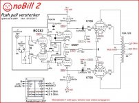
A possible way to put a balanced input on the Bill 2.
Mona
That's a lot like what I'm doing now. I ended up placing 100r resistors on the cathodes to apply NFB. It's like a dual-dual differential. There's probably a name for it.
A possible way to put a balanced input on the Bill 2.
Mona
Yes, your schematics, and the one shown in #35, btw, are perfectly symmetric amplifiers. But what to do if you want to add global NFB in order to achieve lower THD, wider frequency response, higher damping factor etc.?
Myself didn't find any solution for that so far in my also perfectly symmetric Circlotron monoblocks that I've built more than ten years ago. So I went to use transformers, being still in search of an electronic (hopefully with tubes...) solution.
Best regards!
Last edited:
The problem with feedback is a symmetrical source.The Bill2 has an OPT with 0-4-8Ω, no 16Ω. With a 16Ω out you can have two outputs same voltage opposite phase by taking the 4Ω tap as a common, 0 is one phase and 16 the other.Those two can be feed back to the cathodes of the first stage.
Another solution is a floating winding on the OPT to put between the cathodes first stage.
Mona
Another solution is a floating winding on the OPT to put between the cathodes first stage.
Mona
The problem with feedback is a symmetrical source.The Bill2 has an OPT with 0-4-8Ω, no 16Ω. With a 16Ω out you can have two outputs same voltage opposite phase by taking the 4Ω tap as a common, 0 is one phase and 16 the other.Those two can be feed back to the cathodes of the first stage.
Another solution is a floating winding on the OPT to put between the cathodes first stage.
Mona
Like this?
Attachments
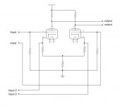
The circuit above is what? A LTP made up of two differential amplifiers?
I found the issue I was having with my simulations. When I calculated the turns ratio, I came up with 33:1. That is plate to plate turns but I entered 33 for each winding in the simulator and plate to plate ended up 66 turns. So my opt primary impedance was much too high. This explained why I'm clipping my input stage before I reach required output power.
I found the issue I was having with my simulations. When I calculated the turns ratio, I came up with 33:1. That is plate to plate turns but I entered 33 for each winding in the simulator and plate to plate ended up 66 turns. So my opt primary impedance was much too high. This explained why I'm clipping my input stage before I reach required output power.
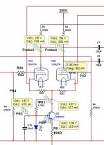
How about like this ?
If the output winding isn't floating the transistor compensate the current in the feedback resistors (within reason).
A irLED for not loosing to much voltage.R6 is uncertain, depends on LED voltage and current gain of the transistor (no high voltage type is needed).
Mona
If the output winding isn't floating the transistor compensate the current in the feedback resistors (within reason).
A irLED for not loosing to much voltage.R6 is uncertain, depends on LED voltage and current gain of the transistor (no high voltage type is needed).
Mona
Attachments
How about like this ?
If the output winding isn't floating the transistor compensate the current in the feedback resistors (within reason).
A irLED for not loosing to much voltage.R6 is uncertain, depends on LED voltage and current gain of the transistor (no high voltage type is needed).
Mona
My output winding is floating. I will keep that in mind though if I decide to wrap feedback around the output stage as well.
How about like this ?
If the output winding isn't floating the transistor compensate the current in the feedback resistors (within reason).
A irLED for not loosing to much voltage.R6 is uncertain, depends on LED voltage and current gain of the transistor (no high voltage type is needed).
Mona
Hi,
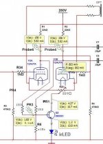
I think you may want to swap R6 and the LED to get your CCS working?
The feedback resistors decrease the tail impedance quite a bit. Does that matter?
Best regards!
Now I see you are using a *tube* power amplifier in a car.
Mbe some "space charge" tubes left over from a 1956 Buick.
FWIW, my Ford SUV already has an inverter for 120VAC.
Edit -- i started this thread on SY's Impasse preamplifier a few years back. It was designed to drive a pair of Nelson's F4's http://www.diyaudio.com/forums/pass-labs/136835-impasse-preamplifier.html
Last edited:
If you swap R6 and LED you get a fixed current source.Any resistance to ground from the feedback cause more current in the tubes, the anode voltage drops.Here the voltage drop on R6 depends on the anode voltages and keep them on the same level, even if the tubes change (other tube, getting old).Now you can experiment with the feedback and keep constant state of the tubes.
Mona
Mona
Last edited:
Now I see you are using a *tube* power amplifier in a car.
Given that, I´m quite certain that a balanced preamp>power amp feed is the LEAST of your problems.
Good luck in your quest ... you´ll need a lot")
I ran a four channel EL84 push pull rig (the one from the tube cad journal with 6n1p, el84 in Pentode mode) behind the back seat in my previous 71 super beetle for over two years, I had it bolted down to the floor with a fancy bracket, and used guitar amp tube retainers. Ran it off of a Euro inverter that had an isolated output, directly rectified for 320 volt supply, and used DC heaters at 6 volts through a 2n3055 boosted LT1085 LDO. I drove that car every single day, for around 3000 miles each month. The amp was dead silent without signal, and never had a single issue even with me driving it like a maniac with my dual carb 1835cc engine.
I've considered building up a screen drive sweep amp for my current daily driver, a 73 super beetle, but I've got other irons in the fire currently as far as big builds go. Sure would be nice to have tubes running my system, considering I drive around 160 miles in this car daily for work six days a week.
Last edited:
I
I've considered building up a screen drive sweep amp for my current daily driver, a 73 super beetle, but I've got other irons in the fire currently as far as big builds go. Sure would be nice to have tubes running my system, considering I drive around 160 miles in this car daily for work six days a week.
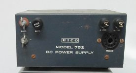
This is a little older than your '73 Beetle. You'll often find these DC-DC converters for Hallicrafters, Heath and Eico ham radio gear:
Attachments
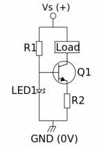
Thanks everyone for the input. I'm a bit confused about the change to the CCS though. Attached is a common circuit for creating a CCS with an LED and transistor. In my case, the cathode is high enough (about 5v) above 0v that I can supply the LED voltage from the cathode. There will be some ripple if the stage becomes unbalanced. A small capacitor at the base might help that. I'm not sure that it's needed.
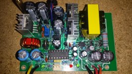
As for the tube amp being mobile, I've already designed and built the smps power supply. It's silent. I'll find a photo in a moment. It has a soft-start 6.3v regulated heater supply (buck) and a 300v (under load) unregulated plate supply (push pull) with an RC to drop to a 250v for the preamp. I use it in a stereo push-pull 6BQ5 amp.

As for the tube amp being mobile, I've already designed and built the smps power supply. It's silent. I'll find a photo in a moment. It has a soft-start 6.3v regulated heater supply (buck) and a 300v (under load) unregulated plate supply (push pull) with an RC to drop to a 250v for the preamp. I use it in a stereo push-pull 6BQ5 amp.
Attachments
- Status
- This old topic is closed. If you want to reopen this topic, contact a moderator using the "Report Post" button.
- Home
- Amplifiers
- Tubes / Valves
- How can I add a balanced input to a tube amplifier?