Ripole folded open baffle loudspeaker designs can now be simulated
This is a great addition. Thanks.
")
Take advantage of the ‘PH’ section. I don’t even know where to begin showing ot produces Things far beyond the crooked paraflex conceptYes.
See the Help file for details.
There is no filling option for band pass systems.
It is a game changer!! And its a hole nother level. Allows things to be seen that never ever were before . Drop information in there That’s relevant to anything else in places in physics that just happens to be described using the circumference of a circle etc. and transferring that into a rectangle(s) and you will see Nirvana(?) lol, I don’t know what to call it fits perfectly aligned everything
Last edited:
Hi Allen,
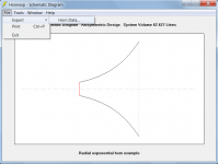
1. Select the File > Export > Horn Data… menu commands from the Schematic Diagram window.
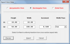
2. Select the Rectangular Horn option.
3. Set the Height and Width values as required.
4. Set the Width Flare to Con.
5. Click the Preview button.
6. Select the Height Profile option.
Kind regards,
David
1. Select the File > Export > Horn Data… menu commands from the Schematic Diagram window.
2. Select the Rectangular Horn option.
3. Set the Height and Width values as required.
4. Set the Width Flare to Con.
5. Click the Preview button.
6. Select the Height Profile option.
Kind regards,
David
Attachments
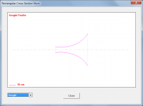


Interesting profile for a horn Allen. The parallel sides at the beginning are tough to get high frequencies past as they reflect and cancel, but under 18mm you get up to 15khertzThank you David.
For what it's worth I'm considering which reasonably straightforward baffling scheme would suit a Yuichi. Looking at a sample horn it may tend toward a vertical baffle done radially.
View attachment 1055329
Similar to this..
View attachment 1055332

I have a basic understanding of hornresp but no idea how to model this:
2 horns attached at the mouth and throat, a tapped offset driver in each. a 3 driver inverted as a double back horn at the mouth and throat (not offset)
no problem modeling individually (at least the 2 offset horns) but not as 1. The amount of offset and possible merging of the final section of both horns is still TBD...any help? Thanks
Ph1 mode will get you a large portion of that?I have a basic understanding of hornresp but no idea how to model this:
2 horns attached at the mouth and throat, a tapped offset driver in each. a 3 driver inverted as a double back horn at the mouth and throat (not offset)
no problem modeling individually (at least the 2 offset horns) but not as 1. The amount of offset and possible merging of the final section of both horns is still TBD...any help? Thanks
Attachments
Take your system models of each and look at how they're connected and you can know whether it's possible with HR or whether you need another tool. If knowing the individual system models is the question, maybe post a sketch of the geometries and talk about your connection location(s).I have a basic understanding of hornresp but no idea how to model this:
2 horns attached at the mouth and throat, a tapped offset driver in each. a 3 driver inverted as a double back horn at the mouth and throat (not offset)
no problem modeling individually (at least the 2 offset horns) but not as 1. The amount of offset and possible merging of the final section of both horns is still TBD...any help? Thanks
Hey guys, i need your help once more.
-> How can i simulate "filling" AND "filter" at the same time?
At the loudspeaker wizzard, i can either select "filling" or "filter" depending on the selected box type.
When i do some filling in the wizzard, it is removed, as soon as i press calculate... so i can not use the "filter" window from the "calculate" window.
Any tips? Am i just too stupid to find it, or is it simply impossible to calculate filter+filling at the same time?
Thanks
Benni
The effects of a filler if you specify it correctly, are shown in the Loudspeaker Wizard. You need to look up the air resistivity of your filler and then enter it correctly.Hey guys, i need your help once more.
-> How can i simulate "filling" AND "filter" at the same time?
At the loudspeaker wizzard, i can either select "filling" or "filter" depending on the selected box type.
When i do some filling in the wizzard, it is removed, as soon as i press calculate... so i can not use the "filter" window from the "calculate" window.
Any tips? Am i just too stupid to find it, or is it simply impossible to calculate filter+filling at the same time?
Thanks
Benni
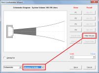
Hi Benni,-> How can i simulate "filling" AND "filter" at the same time?
In the Loudspeaker Wizard:
1. Add the filling material.
2. Select the Memory & Width option.
3. Click the Filter Wizard button.
Kind regards,
David
Attachments
Hornresp Update 5400-220530
Hi Everyone,
CHANGE
A number of minor miscellaneous operational refinements have been made.
For example, it is no longer possible to specify an infinite Ripole loudspeaker, or one that has an odd number of drivers.
Calculated results have not been affected by any of the changes.
Kind regards,
David
Hi Everyone,
CHANGE
A number of minor miscellaneous operational refinements have been made.
For example, it is no longer possible to specify an infinite Ripole loudspeaker, or one that has an odd number of drivers.
Calculated results have not been affected by any of the changes.
Kind regards,
David
Attachments
Regarding the ‘paraflex’ models and ‘PH’ sections: if using 4 equal length resonators(90 cm for example) , and thus 90 cm intervals of folding, and placing outputs to an exit together from both sides of the cone after 3 (x90cm) and 1 (90cm) as ‘front and rear’ youll find the pmin/Vmax is right there and very easy to hear and measure at the baffle edge that splits thetwo sides until that (s4and s9) converge into L45–> s5. As you swing through freqs using a tone generator.
i use 30 cm Centerline for driver entry (its on both sides). and the horn response model is ridiculously accurate/intersstkng and looking into details youd never even suspect unless you start looking at everything with individual frequencies and finetooth comb. Forget sweeps that’s not gonna teach you much and you’re gonna miss all kinds of really interesting things especially out of band where they exist again at log 10x and 100… It seems there’s a flip precisely corresponding to certain frequencies that are landmarks already.
these enclosures are unusual to say the least. But that’s not the only thing you can see him that’s effective using the new section either. It really is nice to be able to tell the simulation what’s happening on both sides of the con upstream and downstream even if it’s in series and feeding like a roar or the Keystone put the front output into the rear and still continue prior to exit stategically.
Hope that helps. Much of the confusion it’s probably because you’re just using sliders and entering kind of random numbers to see what happens instead of the other way around.
if you are trying to tell Horner spot something that already exists and is divided up nice and evenly and appropriately so you have a better chance of not getting frustrated and it seems the results are remarkably accurate as well.
it’s odd because you could use advanced centerline and interrupt an opportunity to see perfect rectangles stacked on top of each other mathematically representing circumference of a circle split as degrees/centimeters(if 360 total) or you could just add up the four segments and split them up that way because
they’re all the same…
The interesting thing is when the rectangles perimeter is pie in math then is three dimensional character broken in half as two perfect cubes disPlaces a sphere, 52.36% And that’s the same as pi divided by six and it’s also the short side of those rectangles and shearAnd that’s the same as pi divided by six and it’s also the short side of those rectangles(2 cubes ) and Sides of the cubes(1).
there’s more to this it gets more complicated but there’s a connection here between clocking (timing) both sides of the driver outputs and the results if you just use perfect rectangles as the shape to a math of a circle in sphere(which contains) . Otherwise it doesn’t turn out right and you have a huge face anomaly at the top of the pass band. And that is a variety of issues that you want to avoid at all costs
Last edited:
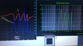
Almost forgot, This (pic as tested and simmed ) is yet another PH1 mode using 80 cm in 4 segments (31.496..” each.). The theme with the circle or the part of the circle irregardless of the units, still seem to provide an opportunity to split things up in a way that simply works.Keeping it simple but accurate:
( when it is lined up perfectly you will see at 430hz and 860 and 1720,3440,4300… -990dB?? At the same time the node and anti-node relationship will be all spaced out perfectly in the response up top (outta bandwidth) and you’ll see what’s going on. There’s no extra or there’s no random mess it’s very well stripped down if you can’t tell you can go slowly through the frequencies and look very specifically to see where it’s a peek and where it isn’t.
At some point it kind of becomes obvious if you’re not lining up to 860 hurting 1720 and someone can be happAt some point it kind of becomes obvious if you’re not lining up to 860 Hz and 1720 we’re not perfectly aligned what you build wont be either. The same will show you it will be a skidmark in response to telltale sign.
in an offset driver mode pi divided by 9 The driver location where you fill in the notch. everything is perfect UTS parameters and cross-sectional areas chosen , it’s exactly at that location. In the double parallel transition or whatever it looks to be changed to (pi divided by six) from both ends instead . Or splitting splitting up the whole thing 12 parts you have a driver entry at 1/12 and 11/12 from each end.
it’s weird but you can figure this out even easier if you just use radians and degress in a 300 cm off the driver pipe (104.72 cm is the sweet spot) or a PH1 mode which has 300 cm between the drivers(30 off each end). (5.236 and 0.5236). Confused yet? Look at pi divided by three. And look at the length of a 300 cm pipe in also driver mode at (0.349065 x 300 is 104.72cm 195.28cm remaining.) 104.719 enter 195.28 is 186.480…also known as the speed of light in miles per second… because everything is based off the number three i suppose…. That being meters per second to the eighth power if we just ignore the fact that somebody decided 2.99792457759 Is the speed of light or the number three as well… because everything would make sense then especially if the speed of sound is 345.6 m/s. Because then 864hz is exactly 1 m in a closed and pipe. And that’s pie times 360 when as you can see that’s pi times 360(in feet/sec when centimeters version of pi is used.
I don’t know the maths in horn response or why it gives such as absolute answer in ‘ph’ mode , but it is indicative of both sides being perfectly ‘ clocked’, and makes sense if you look further into what those are as wave lendths, And the Pythagorean theorem going around the unit circle, as radians as 30 6090 Are 0.5238, 1.0476, 1.5714 and inside the enclosure once the driver entry position is established within those four segments of equal length.
The cross-sectional area is split in half(160/160cm in 320). So all of the short side (80cm) and the last 1/3 (80cm)of the three segment alongside share the same CSA. That is twice the initial 2/3 of the long side(160cm).
What’s your avoiding or what you’ll see if you see me like this versus any other format is that face discontinuity is completely gone soon as you enter the driveWhat’s your avoiding or what you’ll see if you see me like this versus any other form is the removal of the face discontinuity seen in any ‘paraflex’ layout. This he’s addressing all of these things and ensuring that the offset driver entry is accurate and it is specific to both closed ends. If not phase anomaly returns. That discontinuity or break caused by a cross-sectional area change or individual lengths unfolding out of sequence.
I couldn’t stand the ringing or the Undescribable weird extra stuff that happens (or is missing ) when they’re misaligned in the parallel higher order quarter wave types.
Hornresp Update 5400-220606
Hi Everyone,
BUG FIX
The inconsistency in the impulse response results identified in the post linked below, has now been fixed.
https://www.diyaudio.com/community/...nels-advice-needed.375319/page-6#post-7035358
My thanks to silvershadelynx for reporting the problem.
Kind regards,
David
Hi Everyone,
BUG FIX
The inconsistency in the impulse response results identified in the post linked below, has now been fixed.
https://www.diyaudio.com/community/...nels-advice-needed.375319/page-6#post-7035358
My thanks to silvershadelynx for reporting the problem.
Kind regards,
David
Hornresp Update 5400-220619
Hi Everyone,
CHANGE
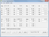
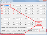
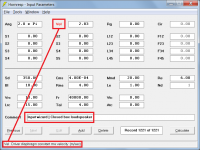
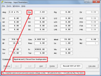
Previously when the current record Eg input field was set to constant velocity (Vel) or constant acceleration (Acc), the setting would carry through to any new record created using the Input Wizard - Attachment 1 refers.
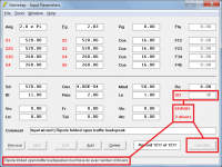
This has now been changed so that Vel or Acc is reset to Eg in the newly-created Input Wizard record - Attachment 2 refers.
Kind regards,
David
Hi Everyone,
CHANGE
Previously when the current record Eg input field was set to constant velocity (Vel) or constant acceleration (Acc), the setting would carry through to any new record created using the Input Wizard - Attachment 1 refers.
This has now been changed so that Vel or Acc is reset to Eg in the newly-created Input Wizard record - Attachment 2 refers.
Kind regards,
David
Attachments
- Home
- Loudspeakers
- Subwoofers
- Hornresp