Hornresp models 4 enclosures just like you would have them in the real world for the purposes of this concept. So there are 4 drivers, and four enclosures. The summing of the horn mouths into one composite horn is done automatically. David can flesh this out better than I can. But I know from using this program for a long, long time that is what happens. I stumbled upon Hornresp in 2000 I believe. And David has made it just a little bit more comprehensive than it was back then. Slightly. ")
You are not the first person to do this and you probably won't be the last.I think I missed multiple speakers tool and mistaken it for the multiple driver function.
In Hornresp "driver" means the drive unit and "speaker" means the complete loudspeaker (enclosure plus driver).
Hello guys,
i am sorry, if this had been asked before, but i searched the whole net for the last 2 days and could not find anything.
Is there any "guide" explaining, how the entry points, s1-s9 values and L12 to L89 look on the real enclosure?
I looked at the system models, also while playing arround in loudspeaker wizzard, so see, wich value refers to what part in the system-model, but i just can not imagine some of those.
I mean... it is simple for direct radiators, there is a nice to understand model of the actual box... but i am really struggeling to understand how for example the paraflex would be assembled, to match the diagram.
Lets say for example paraflex type 3... i just can not get an image of how H7 in the system model is in the real box.. espcially, why i can not change the value of it.
Is there something like a bunch of images of drawn boxes, with the actual parts s1-s9 and such marked in the images?
If not... would someone please be so kind, and draw an image like this for me? Maybe right for the paraflex type 3, so i might hopefully understand it also for the other types.
Thanks a lot in advance
Benni
I have the same problem with the paraflex enclosures.Is there any "guide" explaining, how the entry points, s1-s9 values and L12 to L89 look on the real enclosure?
It's frustrating having a nice model in HR, without knowing how to make it into a physical construction 🤣
The diagrams would have to be wire models to be able to see inside. Or they will not make much sense. But that is setting up design constraints. There might be a way to do this easily. But I am not good enough of a programmer for this anymore. Could also be functional blocks. That might fit Hornresp better.
The diagrams would have to be wire models to be able to see inside. Or they will not make much sense. But that is setting up design constraints. There might be a way to do this easily. But I am not good enough of a programmer for this anymore. Could also be functional blocks. That might fit Hornresp better.
It would be quite simple to dram a schematic view to the box in 2 dimensions. Take the 8th order Bandpass... i can clearly understand where wich dimension and entry-point is. And basically a parafelx is pretty much kind of that.
You could do the same drawing (box-like) for a each horn-type box.
The only problem here is, that there are no informations (or atleast me, and as it seems others aswell, can not find it) about the relationship of the entered parameters in hornrest to the actual position of these on the box.
This does not only count for paraflex... i have the same problem for rearchamber tapped horn with rear chamber and such. When it comes to multiple entry points, my brain is just not able to catch it in the schematic horn overview.
Hi Benni,
Band pass systems are shown as 'boxes' because in most cases it is not possible to represent them as axisymmetric designs. The disadvantages of the box approach are that the dimensions are not true to scale, and the acoustic paths through the system (as assumed by the simulation model) are not immediately obvious. The system model drawings are included in the Loudspeaker Wizard to show how the components, and therefore acoustic paths, are interconnected.
The Hornresp paraflex systems were requested by members of the Facebook group mentioned by Brian. As he suggests, they would be the best people to approach with questions concerning physical layouts. The Facebook link is:
https://www.facebook.com/groups/bassaz/
The value of S7 is calculated automatically from the values of S6, S8, L67 and L78 simply because there is no room left on the main input parameters window for it to be specified independently.
There are so many different possible system configurations that can be specifed in Hornresp that it would be virtually impossible to produce 'box-like' drawings for them all.
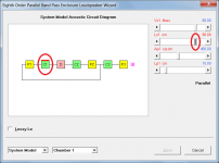
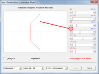
When a Loudspeaker Wizard slider is adjusted the dimension being altered is highlighted in red on the System Model - see Attachment 1.
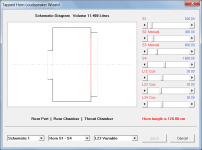
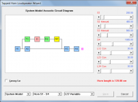
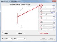
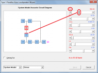
Select the Schematic 1 and System Model options in the Loudspeaker Wizard to get a better understanding of the layout - see Attachments 2 and 3.
Kind regards,
David
It would be quite simple to dram a schematic view to the box in 2 dimensions. Take the 8th order Bandpass... i can clearly understand where wich dimension and entry-point is.
Band pass systems are shown as 'boxes' because in most cases it is not possible to represent them as axisymmetric designs. The disadvantages of the box approach are that the dimensions are not true to scale, and the acoustic paths through the system (as assumed by the simulation model) are not immediately obvious. The system model drawings are included in the Loudspeaker Wizard to show how the components, and therefore acoustic paths, are interconnected.
And basically a parafelx is pretty much kind of that.
The Hornresp paraflex systems were requested by members of the Facebook group mentioned by Brian. As he suggests, they would be the best people to approach with questions concerning physical layouts. The Facebook link is:
https://www.facebook.com/groups/bassaz/
Lets say for example paraflex type 3... i just can not get an image of how H7 in the system model is in the real box.. espcially, why i can not change the value of it.
The value of S7 is calculated automatically from the values of S6, S8, L67 and L78 simply because there is no room left on the main input parameters window for it to be specified independently.
You could do the same drawing (box-like) for a each horn-type box.
There are so many different possible system configurations that can be specifed in Hornresp that it would be virtually impossible to produce 'box-like' drawings for them all.
The only problem here is, that there are no informations (or atleast me, and as it seems others aswell, can not find it) about the relationship of the entered parameters in hornrest to the actual position of these on the box.
When a Loudspeaker Wizard slider is adjusted the dimension being altered is highlighted in red on the System Model - see Attachment 1.
This does not only count for paraflex... i have the same problem for rearchamber tapped horn with rear chamber and such. When it comes to multiple entry points, my brain is just not able to catch it in the schematic horn overview.
Select the Schematic 1 and System Model options in the Loudspeaker Wizard to get a better understanding of the layout - see Attachments 2 and 3.
Kind regards,
David
Attachments
I have tried to model my existing 4th order bandpass enclosure using Hornresp but failed in spectacular fashion. No doubt, human error (me) is the root cause of the problem.
Is there anyone who would like to tell me what data to document and enter the values into Hornresp for me?
Is there anyone who would like to tell me what data to document and enter the values into Hornresp for me?
Seems like we've already done it: https://www.diyaudio.com/community/...sting-bandpass-enclosure.385566/#post-7004901
Respectfully, this is David's thread for his software and, in internet terms, everyone has already been extraordinarily polite and helpful.
http://www.catb.org/~esr/faqs/smart-questions.html
http://www.catb.org/~esr/faqs/smart-questions.html
In retrospect maybe I did assume too much in that if you had imported my attached Lab12c file to your HR IMPORT folder and opened it to see the input fields where all the data was loaded, then all should be clear or at least allow you to ask specific questions rather than a complete tutorial and there's always the HELP file with its 'Find' feature which takes you to all the places in the file it's located.Y'all have been a huge help in acquiring the data, but I have failed in trying to apply the data to a software package like Hornesp.
You're right though, doing it the way we use to required a bit of creativity that one either usually learned by trial n' error or someone posted the way they did it; though again, I/we don't take the time to do the sims to please ourselves.
Hello David!

Wouldnt they result in the same box, just with different numbers in the program? For example like this:

Also... for example 1, how does the program know, where at what exact position of H1 the H7 is entering?
Or schould i see it more like the following imge?

Kind regards,
Benni
Ok, so about that... there is no magic trick about S7? It is just a chamber with the calculated volume, it does not have a special value or something... just random size as wanted, but not possible to enter manually?The value of S7 is calculated automatically from the values of S6, S8, L67 and L78 simply because there is no room left on the main input parameters window for it to be specified independently.
My problem is the understanding of the "joints". What exactly is the difference of these two connections?Select the Schematic 1 and System Model options in the Loudspeaker Wizard to get a better understanding of the layout - see Attachments 2 and 3.
Wouldnt they result in the same box, just with different numbers in the program? For example like this:
Also... for example 1, how does the program know, where at what exact position of H1 the H7 is entering?
Or schould i see it more like the following imge?
Kind regards,
Benni
Last edited:
Sorry for double post, i was to late to edit.
But.. what i was intendet to ask about, is the area, wich the driver is mounted to in H7, like in the following image.
Is it the same as S9? Or is it just the cone area of the driver? Or is it even something completely different?

Sorry, i was thinking about S7 as the wrong thing on the system model... it is just the horn area inbetween s6 and s8, and i can now clearly understand, that you can simply calculate that by the lenght of these two!The value of S7 is calculated automatically from the values of S6, S8, L67 and L78 simply because there is no room left on the main input parameters window for it to be specified independently.
But.. what i was intendet to ask about, is the area, wich the driver is mounted to in H7, like in the following image.
Is it the same as S9? Or is it just the cone area of the driver? Or is it even something completely different?
My problem is the understanding of the "joints". What exactly is the difference of these two connections?
It is really no different to an electrical circuit - in the first case the three elements (H7, H1 and H2) are connected in series, so the "current" passes through each in turn. In the second case the "current" passes through the first element (H7) then divides, with some going into the H1 load and the rest passing through H2.
Or schould i see it more like the following imge?
Yes.
Is it the same as S9? Or is it just the cone area of the driver? Or is it even something completely different?
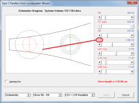
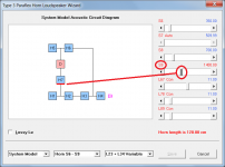
The end of H7 (segment 7) you have highlighted is equal to Sd, the other end is equal to S9, as shown in the attachments.
Attachments
Amazing! Thank you!
That cleared a lot of that fog in my head.
The end of H7 (segment 7) you have highlighted is equal to Sd, the other end is equal to S9, as shown in the attachments.
This is also shown on the System Model diagram, when the Sd and S9 sliders are selected.
Attachments
- Home
- Loudspeakers
- Subwoofers
- Hornresp