It is an enormous voice coil. And you could make a decent arguement that the faraday rings are not really needed in a subwoofer.
And an equally valid arguement, more so in my estimation that Faraday rings would make for a much easier woofer to drive with most power amplifiers. There will be some pretty nasty reactances in the response of the driver.
What impresses me the most about driver is that it has a decent sensitivity. Kind of rare in a Car audio subwoofer.
Hornresp Update 4400-180503
Hi Everyone,
CHANGE 1
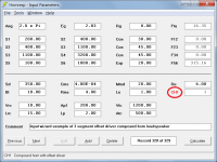
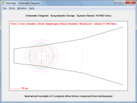
A compound horn system can now have the driver offset in Horn 1.
Attachments 1 to 3 refer.
CHANGE 2
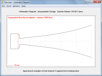
The throat adaptor can now have a conical, exponential or parabolic flare. Previously the flare was fixed at conical. Front loaded horns, back loaded horns and normal compound horns can now in effect have up to five segments.
Attachment 4 refers.
BUG FIX
The driver database file problem described in Posts #8244 and #8249 has now been fixed. My thanks to 'Dix0' for reporting the bug.
Kind regards,
David
Hi Everyone,
CHANGE 1
A compound horn system can now have the driver offset in Horn 1.
Attachments 1 to 3 refer.
CHANGE 2
The throat adaptor can now have a conical, exponential or parabolic flare. Previously the flare was fixed at conical. Front loaded horns, back loaded horns and normal compound horns can now in effect have up to five segments.
Attachment 4 refers.
BUG FIX
The driver database file problem described in Posts #8244 and #8249 has now been fixed. My thanks to 'Dix0' for reporting the bug.
Kind regards,
David
Attachments

Hi David:
These changes are great and moving in the right direction. More segments is always better. Thanks!
Not to be greedy") but, with a conical throat adapter can we have an OS first segment that starts out tangent to that conical throat adapter and then continue with the existing definitions for the remaining segments? Or could we do that in the throat adapter.
but, with a conical throat adapter can we have an OS first segment that starts out tangent to that conical throat adapter and then continue with the existing definitions for the remaining segments? Or could we do that in the throat adapter.
Matching CD exit angle is said to be important; it would nice to be able to see the benefit in simulations.
With 3D printing we can DIY such throats and throat adapters...
Jack
These changes are great and moving in the right direction. More segments is always better. Thanks!
Not to be greedy
but, with a conical throat adapter can we have an OS first segment that starts out tangent to that conical throat adapter and then continue with the existing definitions for the remaining segments? Or could we do that in the throat adapter. Matching CD exit angle is said to be important; it would nice to be able to see the benefit in simulations.
With 3D printing we can DIY such throats and throat adapters...
Jack
with a conical throat adapter can we have an OS first segment that starts out tangent to that conical throat adapter and then continue with the existing definitions for the remaining segments?
Hi Jack,
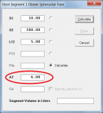
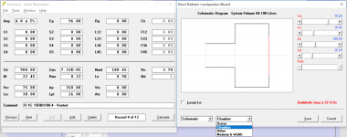
The Horn Segment Wizard can be used to match the throat entry half-angle (AT) of an OS waveguide to the mouth flare tangent angle (Fta) of a conical throat adaptor.
The attached example assumes that the conical throat adaptor has an Fta of 6 degrees, and that the OSW has a throat area of 10 cm^2, a mouth area of 200 cm^2 and an axial length of 5 cm. The Wizard will calculate the OSW flare having an AT of 6 degrees, exactly matching the 6 degree conical throat adaptor Fta.
Segments 2, 3 and 4 cannot be used when an Obl flare is specified.
Kind regards,
David
Attachments
i just searched TH tutorial
Hi Etocynned,
Suggest you search using the keywords 'Hornresp tutorial' instead.
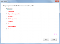
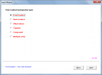
The Input Wizard accessed from under the Hornresp Help menu will allow you to quickly generate an indicative design of the system you have in mind, step by step. You can then adjust the parameter values as required for your specific project.
Kind regards,
David
Attachments
Yeah, that HCCA-152 was certainly a good test and validation that the semi-inductance model accounts for the disparity between modeling and measuring that JAG was seeing in these type of drivers. I will keep you in mind for Beta testing as I get my spreadsheet cleaned up. Sadly I have many irons in the fire and don’t work nearly as fast as DMcBean.Excellent...Glad I could help out. The final match looks quite good. If you do end up with a spreadsheet I wouldn't mind a copy. It may save me a bit of time and match up even better than what I have been doing. I picked the HCCA-152 since it was about the worst case scenario out of all of the drivers I've tested. Huge 4" overhung coil, big motor with a lot of steel in the top plate and pole piece and no shorting rings.
@David McBean,
When do you sleep?!?!
@David McBean,
When do you sleep?!?!
Hi bolserst,
When I'm tired
.Kind regards,
David
Hi keantoken,
The Hornresp wavefront simulator uses a relatively simple "ripple tank" model. You are definitely asking too much of it.
.
Kind regards,
David
So, I may be asking too much of the wavefront simulator, but do you think it would be possible to have a dampening material like cloth or foam?
The Hornresp wavefront simulator uses a relatively simple "ripple tank" model. You are definitely asking too much of it
.I tried using a spray of dots but it only resulted in spontaneous biogenesis of ant colonies.
.Kind regards,
David
Hornresp Update 4400-180512
Hi Everyone,
BUG FIX
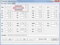
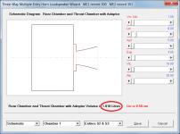
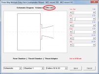
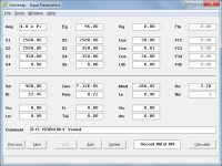
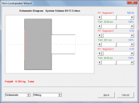
Throat adaptor volume was not being included in the multiple entry horn volume calculations when the Chamber 1 view was shown - see Attachment 1.
This has now been fixed - see Attachment 2.
Kind regards,
David
Hi Everyone,
BUG FIX
Throat adaptor volume was not being included in the multiple entry horn volume calculations when the Chamber 1 view was shown - see Attachment 1.
This has now been fixed - see Attachment 2.
Kind regards,
David
Attachments
I'm trying here to work out how to model a humble vented box with acoustic lining.
Hi Andreas,
It is possible to specify acoustical lining in a closed rear chamber using Fr and Tal, or to specify a port tube in a vented rear chamber using using Ap and Lpt, but it is not possible to specify both together. Selecting the 'resonances masked' option will however remove the higher frequency standing-wave box resonances from the predicted response.
It is possible to include absorbent filling material in a vented chamber as shown in the attachments. It is not quite the same as adding a layer of acoustical lining to just the cabinet walls, but it will give you an indication of the effect you are likely to see.
Kind regards,
David
Attachments
I haven't being able to work on simulation lately because my first soon was just burn and he is consuming a lot of my time.
Hi Marcelo,
Congratulations! Good to see that you have got your priorities right
.Kind regards,
David
- Home
- Loudspeakers
- Subwoofers
- Hornresp