I'm also interested in whether, if such a configuration is possible, it can be modelled in hornresp.
Hi andreasmaaan,
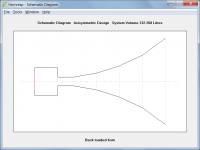
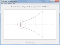
The configuration can be modelled in Hornresp as a back loaded horn (Attachment 1) or as an offset driver horn (Attachment 2).
The port tube has been specified using Ap1 and Lp.
Kind regards,
David
Attachments
Hey David,
I've sent you an email to the address on the Hornresp site about an article coming up. Not sure if you monitor that inbox or not. If not, you can contact me through my website on my signature.
I might well end up referencing parts of this thread, too. PMs will be sent as/when needed.
Cheers,
Chris
I've sent you an email to the address on the Hornresp site about an article coming up. Not sure if you monitor that inbox or not. If not, you can contact me through my website on my signature.
I might well end up referencing parts of this thread, too. PMs will be sent as/when needed.
Cheers,
Chris
Updated to v43& ran into something weird...
If I try to calculate one of my sealed or vented box models I get an "Invalid Result - Change Input Data" error.
Reimporting the driver file (Paste Driver from database) cures the issue & the calculation will then run. However, Exiting Hornresp (even though I clicked "yes" to save the changes) causes the issue to appear once again when v43.00 gets restarted.
Resaving the driver file didn't help either.
The previous version I was using (42.60) doesn't have this issue... which I've gone back to using since I don't currently have a use for the new "Semi-Inductance" specs.
Hi Chris,
Email received - I have sent you a reply.
It is checked daily.
Kind regards,
David
I've sent you an email to the address on the Hornresp site about an article coming up.
Email received - I have sent you a reply.
Not sure if you monitor that inbox or not.
It is checked daily.
Kind regards,
David
Updated to v43& ran into something weird...
If I try to calculate one of my sealed or vented box models I get an "Invalid Result - Change Input Data" error.
Reimporting the driver file (Paste Driver from database) cures the issue & the calculation will then run. However, Exiting Hornresp (even though I clicked "yes" to save the changes) causes the issue to appear once again when v43.00 gets restarted.
Resaving the driver file didn't help either.
The previous version I was using (42.60) doesn't have this issue... which I've gone back to using since I don't currently have a use for the new "Semi-Inductance" specs.
Hi Dix0,
Many thanks for the feedback!
To enable me to investigate the problem, would it be possible for you to post the exported data file for one of your sealed or vented box models that works in V42.60 but not in V43.00, and to also post a copy of the driver file you are using?
Kind regards,
David
Hi all,
I just posted in the subwoofer forum with a question about whether it is possible to horn load a port.
A
The port of a bass reflex enclosure normally produces very low frequency output, around the Helmholtz resonance frequency. This may be way below the cutoff frequency of the horn, so I would think this makes the horn useless.
Of course the presence of the horn may alter the port's function and cause new, possibly interesting, side effects.
My 2 eurocents...
Andre
Hi Andre,
This is the case with the typical vented bass reflex box, however, in this case, this is more like an old-school back loaded horn scoop that you would find in a reggae sound system nowadays.
Hi Dix0,
Many thanks for the feedback!
To enable me to investigate the problem, would it be possible for you to post the exported data file for one of your sealed or vented box models that works in V42.60 but not in V43.00, and to also post a copy of the driver file you are using?
Kind regards,
David
I could, but after some investigating based on what you wanted I checked those files out myself. Then, because I'm such an incorrigible tinkerer with obviously WAY too much time on his hands, I think I found the problem.
So, I'll do you one better... I can tell you how to generate 'em yourself, recreate the problem, & what it seems is going wrong.
Of course, why it's happening & how to fix it is where I 'm gonna come up short... so the bad news is, that part is gong to have to be all on you.

The issue it seems... is not the type of cabinet as I thought... but rather the version of Hornresp the driver file was created with.
I'm not sure what version it started with, but whatever version(s) of Hornresp that added the line "LossyLe=" into a driver file is OK (like 42.60). The issue is any driver file version prior to that (where the last line of the driver file is "Xmax="). I have a few driver files I created with whatever version was in existence back in Feb of 2016, which predates the use of the "LossyLe=" line.
Any driver imported from a file version that does not include the "LossyLe=" line will work, but will only work one time only & while that driver exists in memory. Once the driver is saved either into the data file or saved as a driver file, all the new spec lines for v43.00 are saved as null strings with no value (Re', Leb, etc). That seems to be what is creating the issue.
If the driver file imported includes the "LossyLe=" line (as v42.60 does) and it's value is "0", then all the new v43.00 spec lines are saved with a value of "0" by default & everything works normally.
Interestingly enough, the current "Default Driver" file is one of those old driver files & recreates the issue if you try to use it.
Try this....
1. Add a new record. A copy of the default horn is fine, anything will work.
2. "Paste Driver From Database", using the Default Driver.
3. Click "calculate" if you want just for giggles.... it'll work.
4. Exit Hornresp, Click "Yes" to save changes on the way out.
5. Restart Hornresp & now try to calculate that same record again... it won't work.
If at this point you re-import the driver (same driver, no changes) the calculation will run... & you'll need to do this every time you restart Hornresp, or try to return from running another calculation on a different record.
Just to verify this to myself that I had indeed found the issue, I made a copy of the default driver file & added the line "LossyLe=0" at the bottom below the "Xmax=" line. It worked perfectly.
You can see it in any exported data file. If the driver file imported was an old one that predates the use of the "LossyLe" option, then all the added new spec lines will have no value. If the driver file was from a version that contained the "LossyLe=" line, and that value was "0", then all the new spec lines will also be saved as a value of "0".
So, I'm guessing that's where your issue is... you need to make sure all the new spec lines are assigned (and saved with) a value of "0", even if the "LossyLe=" line is not included in the driver file.
Of the two data export files attached, version "A" is from an old driver file & recreates the issue. Version "B" was created after adding the line "LossyLe=0" to the driver file & works perfectly
Also, simply trying to import & re-save the driver file from v43.00 won't work. All that does is create a driver file that won't work at all (not even the 1st time though), as the driver file will then also get saved with null values.
That's my story & I'm sticking to it... hope I tracked it down for you... or, let me know if you need any more info... I've still got hair left to pull out.
- Dix
Attachments
So, I'll do you one better... I can tell you how to generate 'em yourself, recreate the problem, & what it seems is going wrong.
Hi Dix,
Many thanks for the very comprehensive investigation and analysis of the problem - you have made things exceedingly easy for me
.The fix is as simple as changing "N = 12" to "N = 11" in the code. I will also take the opportunity to update the Default Driver file to the latest format, even though the old file without the "LossyLe=" line will work fine once the coding change is made. A copy of the proposed new default driver file is attached.
Thanks again for reporting this bug - it will be fixed in the next release. In the meantime, you will need to manually add the "LossyLe=" line to your old driver files for them to work.
Kind regards,
David
Attachments
Hi Dix,
The fix is as simple as changing "N = 12" to "N = 11" in the code.
Ah, the ol' typosytis bug... gotta love those.
At least it's an easy fix... that's good news.
For anyone else that runs into this issue in the meantime.... the fix, as noted, is as simple as opening the offending driver file in Notepad and adding the line...
LossyLe=0
as the last line of the file (right below the line "Xmax="), & then re-saving the file.
For example, an old driver file looks like this....
Sd=350.00
Bl=18.00
Cms=4.00E-04
Rms=4.00
Mmd=20.00
Le=1.00
Re=6.00
Pmax=100
Xmax=5.0
Which you will add the LossyLe line to creating this....
Sd=350.00
Bl=18.00
Cms=4.00E-04
Rms=4.00
Mmd=20.00
Le=1.00
Re=6.00
Pmax=100
Xmax=5.0
LossyLe=0
Then everything will function normally in v43.00.
As an additional note, after you type or paste the LossyLe line into the file don't hit enter more than once (thus, entering a blank line) as that also seems to create issues.
Yes, I know this from experience.
I finally got some time to finish analyzing the Orion HCCA-152 files you sent me. Thanks!… I do have close mic data for many sealed cab tests, but I don't include it in the graphs on DB. I'm not sure if I have it for the 2 example drivers exactly but I might. If you need it let me know and I'll see about emailing it to you.
You are right, that is some ridiculous amount of inductance! Approaching 20mH below resonance.
For those unfamiliar with the driver, you can find further details and pics here:
Data-Bass
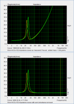
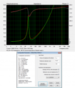
Attachments #1 & #2:
The first thing I did was let ARTA attempt to determine the semi-inductance parameters. As you can see, not a perfect match, but certainly MUCH better than using the single 4.3mH 1kHz value as in the traditional model. Quick, easy, and perfectly acceptable.
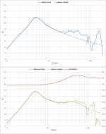
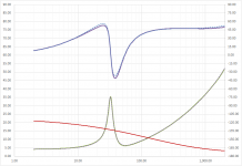
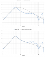
Attachments #3 & #4:
Using my own spreadsheet tool, I was able to get an improved impedance match. The red curve in the impedance plot is the trend of inductance with frequency. The predicted response is just a tiny bit better fit with the near field data than when using the ARTA derived parameters which were already quite close. Also shown is a comparison with the ground plane measurement and the 4Pi-to-2Pi baffle diffraction increment calculated with the BTM diffraction theory. I am working to make a user-friendly version of this spreadsheet for others to use.
Fs: 32.41 Hz
Qes: 0.805
Qms: 5.887
Qts: 0.708
Vas: 47.9 (ltr)
Sd: 890 (cm^2)
Re': 4.100 (ohm)
Leb 2.068 (mH)
Le: 20.922 (mH)
Rss: 61.391 (ohm)
Ke: 0.554 (sH)
Attachments #5:
So, why is the ARTA parameters not quite a perfect fit? Based on the attached article, ARTA determines the driver parameter in two steps. First step is the TSPs of Fs, Qes, Qms, and Vas. It does this based on the shape of the impedance peak. Then, with those values fixed, it uses a least squares fit to try and determine the semi-inductance parameters. The problem is, that with this much inductance the shape of the peak is distorted…steepened on the high side and dished out on the low side. ARTA does use a few tricks to help compensate for this effect. But with this woofer it is a pretty big effect, and the TSP values are slightly tainted. If I subtracted off the semi-inductance from the measured impedance leaving just the voice coil resistance and motional impedance you can see that the curve is symmetric on a log spaced frequency scale as expected. Feeding these curves into ARTA and it comes up with the exact same TSPs as I got with my spreadsheet.
I pretty much follow the same steps ARTA doess, but then(based on recommendation in the AES article) performs a final least-squares-fit with both TSPs and semi-inductance terms freed up from their originally determined values. This allows the distorted peak shape caused by the interaction of the motional impedance and semi-inductance to be properly accounted for.
Attachments
-
 HCCA-152_Zremove_semi-L.png40.4 KB · Views: 297
 -
 HCCA-152_SPLsemi-L.png149.3 KB · Views: 304
 -
 HCCA-152_Zsemi-L.png51 KB · Views: 316
 -
 HCCA-152_SPLtraditional.png138.2 KB · Views: 326
 -
 HCCA-152_TSP_ARTA.png124.3 KB · Views: 321
 -
Estimation of Loudspeaker Driver Parameters Sikora.pdf466 KB · Views: 84
Last edited:
Hi Dix,
A small enhancement will also be made at the same time, so that the source driver database file is automatically updated to the latest format and re-saved, when the driver data is pasted.
Thanks for explaining the interim fix in more detail. My "manually add the LossyLe= line" comment was a bit cryptic.
Kind regards,
David
At least it's an easy fix...
A small enhancement will also be made at the same time, so that the source driver database file is automatically updated to the latest format and re-saved, when the driver data is pasted.
For anyone else that runs into this issue in the meantime.... the fix, as noted, is as simple as opening the offending driver file in Notepad and adding the line...
Thanks for explaining the interim fix in more detail. My "manually add the LossyLe= line" comment was a bit cryptic
.Kind regards,
David

Hi David,
Just a quick trouble-shooting question, please.
Previously, the Maximum SPL function worked regardless how many parameters I had entered. For example, I could enter only the amplifier max voltage and max current, and diaphragm max displacement, and would still get a result.
Now, however, the function only works when I enter all parameters.
I've tried upgrading hornresp but to no avail.
Do you know what might be going on?
Cheers,
Andreas
For example, I could enter only the amplifier max voltage and max current, and diaphragm max displacement, and would still get a result.
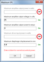
Hi Andreas,
You need to disable the other two parameters by double-clicking their 'On' labels, as shown in the attachment.
From the 'Maximum SPL' section in the Hornresp Help file:
"One or more of the above input parameter options can be selected by double-clicking the On / Off labels."
Kind regards,
David
Attachments
I finally got some time to finish analyzing the Orion HCCA-152 files you sent me. Thanks!
You are right, that is some ridiculous amount of inductance! Approaching 20mH below resonance.
For those unfamiliar with the driver, you can find further details and pics here:
Data-Bass
Excellent...Glad I could help out. The final match looks quite good. If you do end up with a spreadsheet I wouldn't mind a copy. It may save me a bit of time and match up even better than what I have been doing.
I picked the HCCA-152 since it was about the worst case scenario out of all of the drivers I've tested. Huge 4" overhung coil, big motor with a lot of steel in the top plate and pole piece and no shorting rings.
- Home
- Loudspeakers
- Subwoofers
- Hornresp