If there's no advantage at all to doing an end to end asymmetrical location loading then way do it?
It was probably done for the DTS10 to minimize the depth of the box. Also, with the two drivers in tandem instead of side by side, there's a bit more flexibility in the choice of dimensions to achieve the required CSA at S2.
Good info, thanks!Anything else affect high en roll-off?
Almost everything affects high end roll off.
Driver t/s rolloff (mass corners) are calculated like so:
Highest usable frequency... Fh = (2xFs)/qts
and lowest usable frequency... Fl = (qts*Fs)/2
So clearly motor strength and fs are a pretty big deal.
Inductance is also a huge factor.
If a driver fires into a chamber, the chamber will induce high end rolloff. Usually smaller chambers (including no chamber at all) will result in higher extension. Especially if the duct to the outside is very large and/or short.
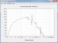
The shape of a horn flare will also dictate high end rolloff. If you tell Hornresp's System Design Tool (Leach's horn math) to make a horn with bandwidth up to and even exceeding 20 khz, it can do it (theoretically, at least). Just set Le to 0, open system design tool, tell it your desired bandwidth and it will find a way to make it happen. It won't be practical but it is theoretically possible because the flare shape has EVERYTHING to do with frequency response. Here's an example.
An externally hosted image should be here but it was not working when we last tested it.
Almost ruler flat across the entire bandwidth Hornresp shows, 10 - 20000 hz using an 18 inch driver.
This is possible theoretically but not in practice because you can't find a driver with Le = 0, you can't make the rear chamber 0.9 liters (the driver wouldn't fit) and you can't use such a small throat (compression ratio is almost 1000:1).
But using flare shape you can dramatically increase the high end extension in certain scenarios.
Just about everything affects high end roll off.
It was probably done for the DTS10 to minimize the depth of the box. Also, with the two drivers in tandem instead of side by side, there's a bit more flexibility in the choice of dimensions to achieve the required CSA at S2.
Sure, but I personally really dislike the DTS 10 and TH_SPUD form factor so I could address the issues by changing the box shape and/or changing the dual driver to a single larger driver. Since I don't see the form factor as any kind of advantage I would never use the end to end driver loading due to the consequences and lack of any advantages.
Almost everything affects high end roll off.
Driver t/s rolloff (mass corners) are calculated like so:
Highest usable frequency... Fh = (2xFs)/qts
and lowest usable frequency... Fl = (qts*Fs)/2
So clearly motor strength and fs are a pretty big deal.
Inductance is also a huge factor.
Just about everything affects high end roll off.
I think that the mass roll off corner formula applies (only) to exponential horns; I know that is where I saw it derived. It apparently doesn't apply on conical horns; HR shows much higher roll off frequencies in typical simulations and my experience is consistent with HR's predictions.
Take a Faital Pro 4FE35 which I have built, measured, and am using crossed over at 1050 Hz on a conical horn:
Fs = 100
Qts = .84
2Fs/Qts = 238 Hz
Of course that was an offset driver whose upper end was limited by the bandpass chamber and the reflection from the CD at the throat of the horn. Response with it mounted at the throat would be to a higher frequency. I've seen other small full range drivers used in place of CDs with responses well past 10 khz on both constant directivity and tractrix horns.
I wouldn't make this point were the context not driver selection for mids on a synergy horn. Its (mis)use will severely and unnecessarily limit your driver choice there.
I think that the mass roll off corner formula applies (only) to exponential horns ...
Yeah, maybe, I was going to comment on my own sim that I just showed too, indicating much higher extension than the Fh mass corner would suggest. T (or M) = 1 so it's a pure exponential horn, not a hyp/ex like I usually sim.
Either way, it would seem that my sim and your comments suggest that the Fl and Fh formulas are not applicable in all cases.
Sorry, I do not have the opportunity to read the whole topic.
Why does the frequency response curve of a speaker in CB have a high-frequency decay? Does this graph come from the Thiele-Small parameters? According to the documentation, the driver has an amplitude response up to 2 kHz, but the program draws a decline.
Why does the frequency response curve of a speaker in CB have a high-frequency decay? Does this graph come from the Thiele-Small parameters? According to the documentation, the driver has an amplitude response up to 2 kHz, but the program draws a decline.
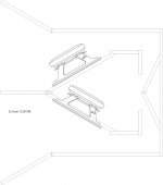
Here is another old school design that i've been looking at. But what I've done is add 2 drivers in push/pull configuration. I'm not sure if this would really be a push/pull because the shape of the plenum is triangular. The drivers are also in the path of the horn similar to a TH. In previous posts just recently I think someone mentioned that drivers in the horn path is a bad thing?
Can this design be simulated in Hornresp? Or would this just be a bad design all together? The PDF contains some dimensions and is full size.
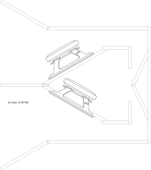
Can this design be simulated in Hornresp? Or would this just be a bad design all together? The PDF contains some dimensions and is full size.
Attachments
Sorry, I do not have the opportunity to read the whole topic.
Why does the frequency response curve of a speaker in CB have a high-frequency decay? Does this graph come from the Thiele-Small parameters? According to the documentation, the driver has an amplitude response up to 2 kHz, but the program draws a decline.
I am no expert on this matter. But it seems to me that Hornresp calculates the effect of the construction, on the basis of electric properties and basic mechanical properties, and does not take into account all relevant other physical properties of the driver. It is a form of simplification, probably with some unknown factors just calculated out of the values you have to provide to give a more realistic estimate. But that's all it is, an estimation, but it usually comes very close to the finished construction.
So (especially on high frequencies) you are often seeing the effects of the box/horn not including the frequency response of each and every driver.
Last edited:
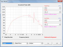
Just me getting "Run time error 6': Overflow" when simulating a classic compact BR enclosure and trying to run the filter wizard?
It seems to work fine on sealed boxes.
Hi KaffiMann,
Thanks for the feedback.
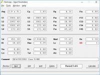
So that I can investigate the problem further could you please post a screenprint of the Input Parameters window for the bass reflex design causing the error.
Are you using the latest release of Hornresp, Product Number 4230-170827?
Kind regards,
David
Why does the frequency response curve of a speaker in CB have a high-frequency decay?
Hi Orion33,
If you are looking at the combined output then you are seeing the power response (non-directional) rather that the pressure response (directional) which is why the high frequency performance seems less. The pressure responses of the two individual outputs can be shown using the Directivity tool, but not the pressure response of the combined output (because the precise relative positions of the two outputs are not known to Hornresp).
Kind regards,
David
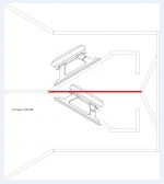
Can this design be simulated in Hornresp?
Hi johnnyjo,
Using the principle of images, assume that the chamber is split into two as shown in the attachment and simulate one half of the enclosure as a tapped horn with a single driver, with the "half system" radiating into half the actual space (for example, if the whole system is intended to radiate into 2 x Pi then simulate the half system radiating into 1 x Pi). Having only four segments available, you will need to approximate the expansion rate of the horn.
Kind regards,
David
Attachments
Hi KaffiMann,
Thanks for the feedback.
So that I can investigate the problem further could you please post a screenprint of the Input Parameters window for the bass reflex design causing the error.
Are you using the latest release of Hornresp, Product Number 4230-170827?
Kind regards,
David
Hello!
Yes it is the newest version.
Here you are.
")
Thank you for a wonderful program, it is very frequently used.
Is there any way I can donate as a small token of my appreciation?
Attachments
Hi KaffiMann,
Thanks for the information. Unfortunately I have not been able to replicate the problem you are experiencing, using your input parameter values. The Filter Wizard opens just fine for me. You could perhaps try importing the attached file, which is an exported copy of the record I entered. If it works, then it would seem that the filter data in your original record must be corrupted in some way. If it doesn't work, then I have no idea what might causing the overflow message.
Thanks for your kind offer of a donation, but knowing that Hornresp is appreciated and that you find it to be useful, is more than enough for me.
Kind regards,
David
Here you are.
Thanks for the information. Unfortunately I have not been able to replicate the problem you are experiencing, using your input parameter values. The Filter Wizard opens just fine for me. You could perhaps try importing the attached file, which is an exported copy of the record I entered. If it works, then it would seem that the filter data in your original record must be corrupted in some way. If it doesn't work, then I have no idea what might causing the overflow message.
Thank you for a wonderful program, it is very frequently used.
Is there any way I can donate as a small token of my appreciation?
Thanks for your kind offer of a donation, but knowing that Hornresp is appreciated and that you find it to be useful, is more than enough for me
.Kind regards,
David
Attachments
Just noticed there is a 1 byte difference between your file and the one I imported from a previous version of hornresp, think it was v42. The filenames are the same length. Something must have happened during exporting/importing I guess.
Maybe I could send you a bottle or two of homemade blueberry wine instead?
Maybe I could send you a bottle or two of homemade blueberry wine instead?
Timely post! I just discovered this last night experimenting with the directivity tools. The term "power" should have been an obvious clue, right?If you are looking at the combined output then you are seeing the power response (non-directional) rather that the pressure response (directional)....
Hi KaffiMann,
Just to clarify - does this mean that the record I posted works okay, and does not generate the overflow error?
.
Kind regards,
David
Just noticed there is a 1 byte difference between your file and the one I imported from a previous version of hornresp, think it was v42. The filenames are the same length. Something must have happened during exporting/importing I guess.
Just to clarify - does this mean that the record I posted works okay, and does not generate the overflow error?
Maybe I could send you a bottle or two of homemade blueberry wine instead?
.Kind regards,
David
The term "power" should have been an obvious clue, right?
Hi Pano,
As far as I am concerned, yes, but my decision to use the term "power response" has proved to be a controversial one, to say the least
.http://www.diyaudio.com/forums/subwoofers/119854-hornresp-637.html#post4754696
Kind regards,
David
- Home
- Loudspeakers
- Subwoofers
- Hornresp