woofers on the side of a horn feeding into the horn through ports in the horn wall are analyzed as bandpass chambers. A bandpass chamber typically has a peaked response before a low pass cutoff. The amount of air trapped between the woofer cone and the horn wall affects the lowpass cutoff frequency. Reducing the amount of air via a plug as pictured raises the cutoff frequency of that low pass filter. Most want to raise it as high as possible to allow a higher XO frequency, taking strain off the compression driver.I'm curious about this comment. I've seen some horn designs where a type of filler (wood or molded foam) is placed on the baffle so that when the driver is attached the filler sits inside taking up space in the cone. This is used to reduce the volume in front of the cone. I've read that this helps improve midrange, but I'm sure it has more of an effect than just midrange frequency. And I wonder if this somehow affects fidelity.
Can anyone explain what effect this has of reducing the enclosed volume of the speaker cone in horn-loaded designs?
And how is this accurately simulated using Hornresp?
In HR, the Vtc parameter represents the volume of air trapped between the cone and the horn wall. Also note that the area (Ap) and length (Lpt) of the ports through the horn wall also affect the response and can be tuned to affect the slope of the roll off.
 Anything else affect high en roll-off?
I'm curious about this comment. I've seen some horn designs where a type of filler (wood or molded foam) is placed on the baffle so that when the driver is attached the filler sits inside taking up space in the cone. This is used to reduce the volume in front of the cone. I've read that this helps improve midrange, but I'm sure it has more of an effect than just midrange frequency. And I wonder if this somehow affects fidelity.
Can anyone explain what effect this has of reducing the enclosed volume of the speaker cone in horn-loaded designs?
And how is this accurately simulated using Hornresp?
It does effect the midrange. And an accurate plug such as you have in the picture can indeed be modeled in Hornresp providing that distance from the cone is uniform. You can very accurately estimate the cone area by using the wizard associated to the Vtc field. Double click on it and you will see the wizard that allows you to measure and input the cone dimensions.
Then adapting a constant distance plug such as you show you can model it in Hornresp as a throat coupling chamber.
The effects of a plug like this are indeed to permit higher frequency response to be generated at useful levels in the design. But this is not some magic bullet that will allow high frequency response out of any woofer or midrange. That is more determined by the drivers inductance than by this type of application. If the driver has a low inductance and due design diligence is used you can create a rather wide bandwidth response from this type of a setup.
Question for the Hornresp gurus.
If you use two woofers in the Tapped Horn which dimensions do you enter for L12 , S2, S3 etc. Do you average the dimensions for the two woofers, use either the smaller or the larger of the two possible ones?

Also, if I used two drivers, but arranged them like in the DTS-10, what would be the proper dimensions to use?
I'm thinking of making a little more powerful version of the 38Hz Tang Band TH from Volvotreter.de by using two of the 6" woofers in series.
http://volvotreter.de/downloads/TangBand_W6-1139SC_38Hz_TH_Rev_1.pdf
If you use two woofers in the Tapped Horn which dimensions do you enter for L12 , S2, S3 etc. Do you average the dimensions for the two woofers, use either the smaller or the larger of the two possible ones?
Also, if I used two drivers, but arranged them like in the DTS-10, what would be the proper dimensions to use?
An externally hosted image should be here but it was not working when we last tested it.
I'm thinking of making a little more powerful version of the 38Hz Tang Band TH from Volvotreter.de by using two of the 6" woofers in series.
http://volvotreter.de/downloads/TangBand_W6-1139SC_38Hz_TH_Rev_1.pdf
Last edited:
Hornresp lumps the drivers into a single unit. It just increases in size if you increase the number of drivers. And for the design you are asking about as long as the drivers are within a 1/4 wavelength of the frequency being reproduced they act as one driver in the first place.
If you want the math a simple number is speed of sound equals 1125 feet per second. Divide 1125 by the frequency of interest and you get the dull wavelength of that particular sound frequency.
1125/30(hertz) = 37.5 feet
1125/100(hertz) = 11.25 feet
Reflections start to matter at the 1/4 wavelength so :
37.5/4 = 9.375 feet quarter wavelength of 30 hertz as above.
Thanks, I understand the physics of sound wave lengths. My question arose because certain parameters seem to have a large effect on the simulation. Especially L12 and S2 affect the outcome, as they are responsible for the compression ratio. With two woofers, the one closer to the narrow end has higher compression than the one further down the line. That's why I asked if maybe the average would be the correct length and width. Are you saying that the right thing to do is to stick with the woofer closer to the narrow end?
And for the design you are asking about as long as the drivers are within a 1/4 wavelength
1125/30(hertz) = 37.5 feet
Reflections start to matter at the 1/4 wavelength so :
37.5/4 = 9.375 feet quarter wavelength of 30 hertz as above.
What does this mean exactly?
Does this refer to the distance between each driver and that the drivers should be within 9.375 ft of each other to stay within a 1/4 wavelength?
Also in reference to the photo, it looks like a push/pull arrangement in a tapped horn. Can push/pull be modeled in Hornresp?
Those are not push pull, they are just mounted where and how they physically fit. They are wired to work in tandem.
As to the quarter wave, mwmkravchenko was saying that as long as the drivers are relatively close they act like one.
For bass frequencies, "relatively close" means closer than a few feet. For tweeters "relatively close" would be less than one inch. It all depends on the frequencies reproduced and their wave lengths.
In Hornresp the best you can do with dual drivers is sim them as one larger composite driver located at the acoustic center of the two physical drivers.
If you sim this arrangement in Akabak using two distinct drivers at different locations though, you will see that the two drivers will have a significantly different load if they are one in front of the other in the horn path.
The best thing to do usually is to try to keep them as close to the closed end as possible, if practical put them side by side or firing into each other to keep the acoustic center as close as possible to the closed end.
If they are end to end in the horn path there's no way to get them close enough to endure the same loading. 1/4 wave rules won't help much here, even if they did you would want a frequency at the top of the passband, not the bottom.
Josh Ricci talks about this uneven driver loading at length, I think you can find his dialogue on this phenomenon in the MAUL thread on the data-bass forum.
Found it. There's a bit in this post - ZOD Audio M.A.U.L. Test Results and Discussion - Page 2 - Bass Projects - Data-Bass Forums
At this point I started up Akabak and did the detailed script which included the drivers loading into different points along the horn path. The results were not good. The response changed some but the big concern was that the drivers behaved much different from each other. The excursion profiles vs frequency were different and it became quite uncontrolled on the drivers furthest from the throat. This simulation showed greatly reduced output before the drivers met xmech due to this and other issues.
But there's a lot more in this post, too much to copy and paste, so just read the linked post here - ZOD Audio M.A.U.L. Test Results and Discussion - Page 2 - Bass Projects - Data-Bass Forums
Good description of the issue and lots of pics in this post.
And then there's a bit more commentary and pictures in this post - ZOD Audio M.A.U.L. Test Results and Discussion - Page 3 - Bass Projects - Data-Bass Forums
He's laid out a fair case for never putting drivers end to end along the horn path unless you simulate with Akabak first and determine that it's an acceptable trade off. I'd probably never do it.
Sometimes my wacky sense of humor getts under Anthony's (just a guy) skin.
...
As for me posting technical info. What would you like to see Anthony?
Your entire post text was "Pill time." and it was directed at me.
I don't find this funny, if you want to refute my previous post do it in technical fashion. After you do that you can include a little poke at the end, I won't mind if it comes following a coherent technical reply. On it's own though, I don't care for it.
Found it. There's a bit in this post - ZOD Audio M.A.U.L. Test Results and Discussion - Page 2 - Bass Projects - Data-Bass Forums
At this point I started up Akabak and did the detailed script which included the drivers loading into different points along the horn path. The results were not good. The response changed some but the big concern was that the drivers behaved much different from each other. The excursion profiles vs frequency were different and it became quite uncontrolled on the drivers furthest from the throat. This simulation showed greatly reduced output before the drivers met xmech due to this and other issues.
But there's a lot more in this post, too much to copy and paste, so just read the linked post here - ZOD Audio M.A.U.L. Test Results and Discussion - Page 2 - Bass Projects - Data-Bass Forums
Good description of the issue and lots of pics in this post.
And then there's a bit more commentary and pictures in this post - ZOD Audio M.A.U.L. Test Results and Discussion - Page 3 - Bass Projects - Data-Bass Forums
He's laid out a fair case for never putting drivers end to end along the horn path unless you simulate with Akabak first and determine that it's an acceptable trade off. I'd probably never do it.
Thanks, this is the type of info I was looking for.
OTOH, I went back to the help files and I realized that I was misreading some of the parameters because the graphic is suggestive of things it does not really represent.
I guess if the first section of the horn is straight as opposed to expanding, the behavior of the drivers would be more consistent. But I will read up on this some more. I really like how Danley mounted the first driver in a chamber before the horn even officially starts. I plan on trying this arrangement and hopefully it works well even if I can't simulate it beforehand.
I guess if the first section of the horn is straight as opposed to expanding, the behavior of the drivers would be more consistent.
If you read the links I provided you will see that ALL of the issues were due to placing multiple drivers at different locations in the horn. And these are serious problems.
Making the horn path straight instead of flared might cause some small irregularities but nothing near the problems from loading drivers at different points along the length of the horn flare.
I really like how Danley mounted the first driver in a chamber before the horn even officially starts. I plan on trying this arrangement and hopefully it works well even if I can't simulate it beforehand.
As far as I'm concerned the horn starts at the closed end regardless of whether there's an oddly shaped flare or not. If you look at the DTS 10 thread at avsforum you will see a LOT of broken drivers. In many cases is just a single driver that failed. I haven't read enough of the thread to say it was due to this issue that Ricci brings up in the links I provided or not, but I would be very wary of replicating this end to end driver loading. There's no real advantage and plenty of reason not to.
In HR, the Vtc parameter represents the volume of air trapped between the cone and the horn wall. Also note that the area (Ap) and length (Lpt) of the ports through the horn wall also affect the response and can be tuned to affect the slope of the roll off.
Just to clarify - Ap and Lpt specify a rear chamber port. Use Ap1 and Lp to specify a port between the throat chamber and the horn wall.
Hi Pano,
You don't know what you have been missing - welcome to the club") .
.
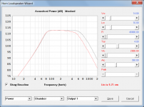
Primarily the throat chamber - it acts as a low pass filter. The effect on the power response can be demonstrated by taking a copy of the default record, opening the Loudspeaker Wizard, and adjusting the value of the Vtc slider. High frequency performance is of course also affected by the driver parameter values - try increasing the Mmd and Le slider values.
Kind regards,
David
Finally, after all these years - I've learned to use Hornresp.
You don't know what you have been missing - welcome to the club
.In simulating front loaded horns, what causes the low pass behavior?
Primarily the throat chamber - it acts as a low pass filter. The effect on the power response can be demonstrated by taking a copy of the default record, opening the Loudspeaker Wizard, and adjusting the value of the Vtc slider. High frequency performance is of course also affected by the driver parameter values - try increasing the Mmd and Le slider values.
Kind regards,
David
Attachments
If you read the links I provided you will see that ALL of the issues were due to placing multiple drivers at different locations in the horn. And these are serious problems.
Making the horn path straight instead of flared might cause some small irregularities but nothing near the problems from loading drivers at different points along the length of the horn flare.
As far as I'm concerned the horn starts at the closed end regardless of whether there's an oddly shaped flare or not. If you look at the DTS 10 thread at avsforum you will see a LOT of broken drivers. In many cases is just a single driver that failed. I haven't read enough of the thread to say it was due to this issue that Ricci brings up in the links I provided or not, but I would be very wary of replicating this end to end driver loading. There's no real advantage and plenty of reason not to.
We need that 5th segment in HR to accurately model inline drivers within the same TH path.
Funny thing is that I remember David posting sims of multiple segment tapped horns simmed in AkaBak against a simplified horn in Hornresp. And they were very close to each other.
It may simply be a situation where we think our attention to details in a tapped horn simulation is only serving our own interests and not the actual accuracy in calculation?
It may simply be a situation where we think our attention to details in a tapped horn simulation is only serving our own interests and not the actual accuracy in calculation?
Funny thing is that I remember David posting sims of multiple segment tapped horns simmed in AkaBak against a simplified horn in Hornresp. And they were very close to each other.
I could also show examples that would not be close at all when compared. It depends on how close the horn is to it's single segment comparison horn in the first place.
It may simply be a situation where we think our attention to details in a tapped horn simulation is only serving our own interests and not the actual accuracy in calculation?
Are you talking about the dual (or more) drivers located at different points along the horn path? The easy way to find the answer is to simulate it accurately with Akabak like Ricci did, and his examples are troubling at best when it comes to trying to make a blanket statement about the issue.
Obviously the closer the drivers are to the same location along the horn flare, the less the uneven loading will be. So two 4 inch drivers placed end to end won't make a massively significant difference, but two 21 inch drivers placed end to end is likely a very terrible idea.
Still, the issue can be entirely avoided by placing both drivers into the same location along the horn flare, you can even have them placed to ensure force canceling and possibly even reduction of even order harmonics. What else do you need? If there's no advantage at all to doing an end to end asymmetrical location loading then way do it?
If you are talking instead about more segments being more accurate - more segments are more accurate. Period. It could be slightly more accurate or a lot more accurate, you won't know until you sim accurately.
Last edited:
- Home
- Loudspeakers
- Subwoofers
- Hornresp