A render of the Hornresp:
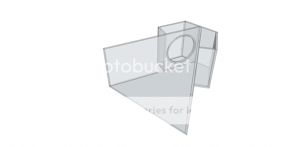
That has a rear chamber - i wonder if that is the difference?
If you send the code to your email account on any of the major email services (gmail for example) as an attachment (and encrypt if you have to), you will have a very well preserved backup copy as it is maintained on who knows how many cloud server farms...
Having a printed out paper copy of the code can always be OCR'd back too....
Hi xrk971,
Many thanks for the tips!
I have archived a copy of the latest Hornresp code to my email account as suggested. In the interests of preserving trees though, I won't try the printed paper copy option. A listing of the current source code would fill more than a thousand A4 pages
") .
.Thanks again - I am a lot happier now that I have a backup copy stored "off-site"
.Kind regards,
David
That's interesting, Hornresp does not predict as much gain on the top end for a OD FLH. Can you post the script? Akabak does not calculate using parabolic expansion, could that be the difference?
NeoDan,
Here is the Akabak script for the Legis horn. The geometry is just as he has drawn. I assumed that he wanted to drivers to be mounted as close to the back as possible, so based on diameter of the driver, I determined it needed 200 mm of clearance from centerline to the back edge of the horn sidewall. Based on a 30 deg half angle, this places the axial distance from the vertex to the driver injection point at 173 mm. It is quite a simple geometry and I assumed a linear expansion (not conical, or exponential). I just noticed that I was using a -12dB/oct HPF and not a -24dB, so maybe even more power can be eeked out of this - not that it is needed though
X
Code:
| ### Model of Legis open back dual driver 1 m x 1m x 50 cm high horn with Dual Deltalite 15's
| by xrk971
| July 3, 2014

System 'Legis Horn'

Def_Const

{

| ### input parameters ###

| ### Define exterior physical size of speaker

Width = 1.00  ;   | width at mouth in meters
Height = 0.50 ;   | height of speaker in meters
Depth = 1.00  ;   | depth of speaker from cusp to mouth in meters

Speaker_pos=0.25;  | Speaker height above floor in meters
Dist_wall=2.0;     | Speaker distance from back wall in meters

| Horn geometery

S0=0.01    ;  |width of vertex in meters (small value)
S1=0.173   ;  |width at driver center assuming 200 mm center to edge distance for driver in meters
L01=0.173  ;  |distance from vertex to driver on centerline cos(30deg)*200mm=173mm
S2=1.00    ;  |width at mouth in meters
L12=0.827  ;  |distance from driver at centerline to mouth in meters

}

Def_Driver  'Deltalite15'  | Eminence Model Delatalite II 15  4.8 mm xmax, 99.2dB, Qts 0.38
  SD=856.3cm2   |Piston
  fs=42Hz
  Mms=72g
  Qms=4.56
  Qes=0.41
  Re=5.29ohm
  Le=1.15mH
  Bl=15.7Tm
  Vas=204L


| Speaker with horn axis CL at Speaker_pos above floor and Dist_wall away from back wall
Def_Reflector  HorizEdge
Bottom={Speaker_pos}  Top={Dist_wall+Depth}
HAngle=0  VAngle=0

Filter 'HighPass' |Highpass filter -12dB/oct BW
fo=75Hz vo=1
{b2=1;
a2=1; a1=1.414214; a0=1; }


| Define driver to be used and wired in parallel (left driver when viewed from front
Driver Def='Deltalite15' 'Driver 1'
Node=1=0=11=201

| Right driver when viewed from front
Driver Def='Deltalite15' 'Driver 2'
Node=1=0=11=202

| Backside of drivers are radiators angled at 30 deg back - left driver angled left back
Radiator  'Rear_Rad1'  Def='Driver 1'    Node=201
    x=-0.173m  y=0  z=-0.827m  HAngle=-30  VAngle=0
    WEdge={Width/2}  Hedge={Height/2}  Reflection
Label=10

| Right driver back radiator angled back right
Radiator  'Rear_Rad2'  Def='Driver 2'    Node=202
    x=0.173m  y=0  z=-0.827m  HAngle=30  VAngle=0
    WEdge={Width/2}  Hedge={Height/2}  Reflection
Label=20

| ### HORN WAVEGUIDE

Waveguide 'Horn Seg 1'  | From vertex to driver at node=11 (both drivers excite node 11
Node=10=11
STh={S0*Height}
SMo={S1*Height}
Len={L01}

Waveguide 'Horn Seg 2'  | From driver injection point to mouth
Node=11=12
STh={S1*Height}
SMo={S2*Height}
Len={L12}

| ### Main horn mouth radiator
Radiator  'Horn Mouth'  Def='Horn Seg 2'    Node=12
    x=0  y=0  z=0  HAngle=0  VAngle=0
    WEdge={Width/2}  Hedge={Height/2}  Reflection
Label=30
Last edited:
Hi xrk971,
Many thanks for the tips!
I have archived a copy of the latest Hornresp code to my email account as suggested. In the interests of preserving trees though, I won't try the printed paper copy option. A listing of the current source code would fill more than a thousand A4 pages
Thanks again - I am a lot happier now that I have a backup copy stored "off-site"
Kind regards,
David
You are welcome! It is amazing that we have 2GB of free 100% uptime fully redundant backups accessible from anywhere in the world from any free email account. The low cost of disk drives I suppose. Hope you don't mind the couple of OT posts of late regarding the Legis horn. If we discuss much further I will move to its own thread.
Hope you don't mind the couple of OT posts of late regarding the Legis horn.
Not a problem
.That has a rear chamber - i wonder if that is the difference?
I cheked and the "acoustical power" graph of Akabak is more like hornresp's acoustic power graph. I cannot choose the hornresp to show tools -> directivity -> response -> 0deg with the NEO Dan's sim for some reason (the whole directivity-option is grayed-out). Why is that? I think it would be the corresponding graph for the "acoustical pressure" graphs of Akabak that you attached previously.
Does the Akabak and/or Hornresp take into account the "mass break point" of the driver? I calculated it to be approx. 205Hz with that Eminence driver (Bl^2 / pi * Re * Mms in kilograms [ie. 72g = 0,072kg]). I'm not sure does that apply since the compression ratio at throat is miniscule (or non-existent) and the drivers do not have a back chamber. But, if Akabak does not take that into account and hornresp does, it would also alter the graphs.
Last edited:
I cheked and the "acoustical power" graph of Akabak is more like hornresp's acoustic power graph. I cannot choose the hornresp to show tools -> directivity -> response -> 0deg with the NEO Dan's sim for some reason (the whole directivity-option is grayed-out). Why is that? I think it would be the corresponding graph for the "acoustical pressure" graphs of Akabak that you attached previously.
If I understand the drawing correctly, the sim is an OD (offset driver horn), which logically requires at least two segments. The directivity tool is only available on one segment horns (which necessitates using Nd instead of OD). You could make a comparable one segment horn with the drivers firing into the throat just to see what effect different angles have on the response, and then imagine that as a transfer function to apply to the OD simulation. But as far as I know there's no other way to get directivity response of an OD horn in hornresp.
If I understand the drawing correctly, the sim is an OD (offset driver horn), which logically requires at least two segments. The directivity tool is only available on one segment horns (which necessitates using Nd instead of OD). You could make a comparable one segment horn with the drivers firing into the throat just to see what effect different angles have on the response, and then imagine that as a transfer function to apply to the OD simulation. But as far as I know there's no other way to get directivity response of an OD horn in hornresp.
Ok, that's too bad for multisegment horns!
The difference in power response (lighter trace) and front/0deg frequecy response (darker trace) is quite big in "similar-ish" (or maybe not) monosegment horn:
An externally hosted image should be here but it was not working when we last tested it.
I am not sure if I understand the nuances of what you guys are trying to do in Hornresp with power and pressure at 0 deg. The type if data I generate with AkAbak is the standard sound pressure plot at zero deg I usually always make. Is there something else I should be setting on AkAbak for you to compare? This is a very simple, albeit complicated by rear firing radiators, 2 segment horn so I hope I did not mess it up. Let me know if you want me to try something g different.
I am not sure if I understand the nuances of what you guys are trying to do in Hornresp with power and pressure at 0 deg. The type if data I generate with AkAbak is the standard sound pressure plot at zero deg I usually always make. Is there something else I should be setting on AkAbak for you to compare? This is a very simple, albeit complicated by rear firing radiators, 2 segment horn so I hope I did not mess it up. Let me know if you want me to try something g different.
The plots you made were the correct ones, ie. the 0deg freq response. At first I mistook Hornresp's power response for a 0deg freq response but they are two (very) different things.
One thing you could try, is to use a 20-60 litre back chamber for the drivers and how that changes the response near the low and upper cutoff points. The chamber could also be tried with a leaking/acoustic resistance port, that would delay the rear wave and control (make narrower) the radiation pattern near the low cutoff. However it might be a bit complicated to simulate!
Legis Horn with sealed rear chamber and with vents
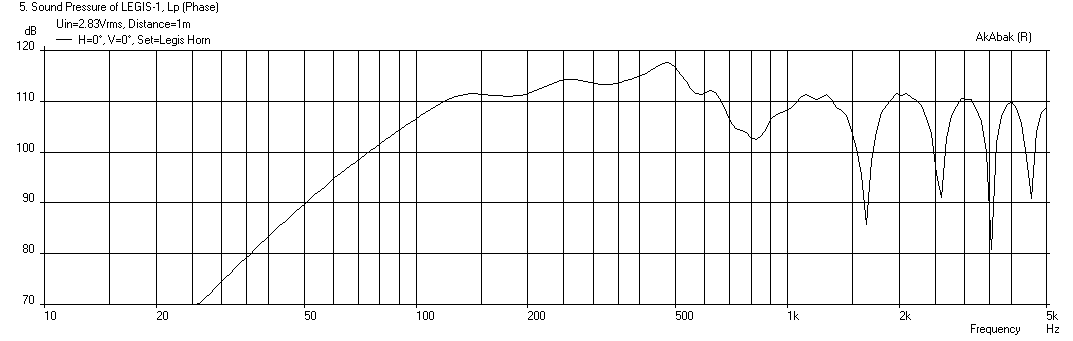
Here is the Legis horn case (a) with open back, case (b) with a 30 liter (ea) sealed back chamber, and case (c) with a 30 liter back chamber that has a 4 in dia x 10 in long vent aimed backwards +/- 60 deg from centerline.
Case (a) open back at 2.83v and 1 meter:
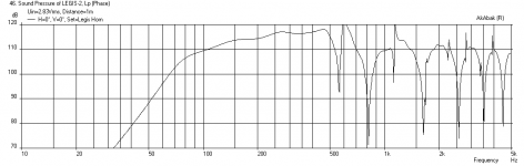
Case (b) sealed 30 liter rear chamber (Q=0.5) at 2.83v and 1 meter:

Case (c) with 30 liter chamber and 4 in dia x 10 in long vent:

The vented rear chamber case obviously has the deepest bass extension. What is interesting is that the open back case loads the cone better than the sealed chamber, and is about the same as the vented case.
Here is the script - remove comment | before the OFF in the Vent Radiator specification to turn vent off.
Looks better between @ 25-30 per driver.
Here is the Legis horn case (a) with open back, case (b) with a 30 liter (ea) sealed back chamber, and case (c) with a 30 liter back chamber that has a 4 in dia x 10 in long vent aimed backwards +/- 60 deg from centerline.
Case (a) open back at 2.83v and 1 meter:
Case (b) sealed 30 liter rear chamber (Q=0.5) at 2.83v and 1 meter:
Case (c) with 30 liter chamber and 4 in dia x 10 in long vent:
The vented rear chamber case obviously has the deepest bass extension. What is interesting is that the open back case loads the cone better than the sealed chamber, and is about the same as the vented case.
Here is the script - remove comment | before the OFF in the Vent Radiator specification to turn vent off.
Code:
| ### Model of Legis open back dual driver 1 m x 1m x 50 cm high horn with Dual Deltalite 15's
| by xrk971
| July 4, 2014
| Version 3 includes rear chambers and option to have vents

System 'Legis Horn 3'

Def_Const

{

| ### input parameters ###

| ### Define exterior physical size of speaker

Width = 1.00  ;   | width at mouth in meters
Height = 0.50 ;   | height of speaker in meters
Depth = 1.00  ;   | depth of speaker from cusp to mouth in meters

Speaker_pos=0.25;  | Speaker height above floor in meters
Dist_wall=2000.0;     | Speaker distance from back wall in meters
Q=0.5 ;  | Q of back chamber
Backchamber_vol=30*0.001  ; | vol in liters

| Horn geometery

S0=0.01    ;  |width of vertex in meters (small value)
S1=0.173   ;  |width at driver center assuming 200 mm center to edge distance for driver in meters
L01=0.173  ;  |distance from vertex to driver on centerline cos(30deg)*200mm=173mm
S2=1.00    ;  |width at mouth in meters
L12=0.827  ;  |distance from driver at centerline to mouth in meters

}

Def_Driver  'Deltalite15'  | Eminence Model Delatalite II 15  4.8 mm xmax, 99.2dB, Qts 0.38
  SD=856.3cm2   |Piston
  fs=42Hz
  Mms=72g
  Qms=4.56
  Qes=0.41
  Re=5.29ohm
  Le=1.15mH
  Bl=15.7Tm
  Vas=204L


| Speaker with horn axis CL at Speaker_pos above floor and Dist_wall away from back wall
Def_Reflector  HorizEdge
Bottom={Speaker_pos}  Top={Dist_wall+Depth}
HAngle=0  VAngle=0

Filter 'HighPass' |Highpass filter -12dB/oct BW
fo=75Hz vo=1
{b2=1;
a2=1; a1=1.414214; a0=1; }


| Define driver to be used and wired in parallel (left driver when viewed from front
Driver Def='Deltalite15' 'Driver 1'
Node=1=0=11=201

| Right driver when viewed from front
Driver Def='Deltalite15' 'Driver 2'
Node=1=0=11=202

Enclosure  'Back chamber 1'  Node=201
Vb={Backchamber_vol}  Qb/fo={Q}  Lb=12in

Duct    'Vent 1'  Node=201=211  | rear vent left
    dD=4in  Len=10in

Enclosure  'Back chamber 2'  Node=202
Vb={Backchamber_vol}  Qb/fo={Q}  Lb=12in

Duct    'Vent 2'  Node=202=212  | rear vent right
    dD=4in  Len=10in

| Backside vent radiators angled at 60 deg back - left driver angled left back
|OFF
Radiator  'Rear_Rad1'  Def='Vent 1'    Node=211
    x=-0.173m  y=0  z=-0.827m  HAngle=-60  VAngle=0
    WEdge={Width/2}  Hedge={Height/2}  Reflection
Label=10

| Right vent radiator angled back right
|OFF
Radiator  'Rear_Rad2'  Def='Vent 2'    Node=212
    x=0.173m  y=0  z=-0.827m  HAngle=60  VAngle=0
    WEdge={Width/2}  Hedge={Height/2}  Reflection
Label=20

| ### HORN WAVEGUIDE

Waveguide 'Horn Seg 1'  | From vertex to driver at node=11 (both drivers excite node 11
Node=10=11
STh={S0*Height}
SMo={S1*Height}
Len={L01}

Waveguide 'Horn Seg 2'  | From driver injection point to mouth
Node=11=12
STh={S1*Height}
SMo={S2*Height}
Len={L12}

| ### Main horn mouth radiator
Radiator  'Horn Mouth'  Def='Horn Seg 2'    Node=12
    x=0  y=0  z=0  HAngle=0  VAngle=0
    WEdge={Width/2}  Hedge={Height/2}  Reflection
Label=30
Attachments


Last edited:
Here is the Legis horn case (a) with open back, case (b) with a 30 liter (ea) sealed back chamber, and case (c) with a 30 liter back chamber that has a 4 in dia x 10 in long vent aimed backwards +/- 60 deg from centerline.
Case (a) open back at 2.83v and 1 meter:
Case (b) sealed 30 liter rear chamber (Q=0.5) at 2.83v and 1 meter:
Case (c) with 30 liter chamber and 4 in dia x 10 in long vent:
The vented rear chamber case obviously has the deepest bass extension. What is interesting is that the open back case loads the cone better than the sealed chamber, and is about the same as the vented case.
Here is the script - remove comment | before the OFF in the Vent Radiator specification to turn vent off.
Code:| ### Model of Legis open back dual driver 1 m x 1m x 50 cm high horn with Dual Deltalite 15's | by xrk971 | July 4, 2014 | Version 3 includes rear chambers and option to have vents System 'Legis Horn 3' Def_Const { | ### input parameters ### | ### Define exterior physical size of speaker Width = 1.00 ; | width at mouth in meters Height = 0.50 ; | height of speaker in meters Depth = 1.00 ; | depth of speaker from cusp to mouth in meters Speaker_pos=0.25; | Speaker height above floor in meters Dist_wall=2000.0; | Speaker distance from back wall in meters Q=0.5 ; | Q of back chamber Backchamber_vol=30*0.001 ; | vol in liters | Horn geometery S0=0.01 ; |width of vertex in meters (small value) S1=0.173 ; |width at driver center assuming 200 mm center to edge distance for driver in meters L01=0.173 ; |distance from vertex to driver on centerline cos(30deg)*200mm=173mm S2=1.00 ; |width at mouth in meters L12=0.827 ; |distance from driver at centerline to mouth in meters } Def_Driver 'Deltalite15' | Eminence Model Delatalite II 15 4.8 mm xmax, 99.2dB, Qts 0.38 SD=856.3cm2 |Piston fs=42Hz Mms=72g Qms=4.56 Qes=0.41 Re=5.29ohm Le=1.15mH Bl=15.7Tm Vas=204L | Speaker with horn axis CL at Speaker_pos above floor and Dist_wall away from back wall Def_Reflector HorizEdge Bottom={Speaker_pos} Top={Dist_wall+Depth} HAngle=0 VAngle=0 Filter 'HighPass' |Highpass filter -12dB/oct BW fo=75Hz vo=1 {b2=1; a2=1; a1=1.414214; a0=1; } | Define driver to be used and wired in parallel (left driver when viewed from front Driver Def='Deltalite15' 'Driver 1' Node=1=0=11=201 | Right driver when viewed from front Driver Def='Deltalite15' 'Driver 2' Node=1=0=11=202 Enclosure 'Back chamber 1' Node=201 Vb={Backchamber_vol} Qb/fo={Q} Lb=12in Duct 'Vent 1' Node=201=211 | rear vent left dD=4in Len=10in Enclosure 'Back chamber 2' Node=202 Vb={Backchamber_vol} Qb/fo={Q} Lb=12in Duct 'Vent 2' Node=202=212 | rear vent right dD=4in Len=10in | Backside vent radiators angled at 60 deg back - left driver angled left back |OFF Radiator 'Rear_Rad1' Def='Vent 1' Node=211 x=-0.173m y=0 z=-0.827m HAngle=-60 VAngle=0 WEdge={Width/2} Hedge={Height/2} Reflection Label=10 | Right vent radiator angled back right |OFF Radiator 'Rear_Rad2' Def='Vent 2' Node=212 x=0.173m y=0 z=-0.827m HAngle=60 VAngle=0 WEdge={Width/2} Hedge={Height/2} Reflection Label=20 | ### HORN WAVEGUIDE Waveguide 'Horn Seg 1' | From vertex to driver at node=11 (both drivers excite node 11 Node=10=11 STh={S0*Height} SMo={S1*Height} Len={L01} Waveguide 'Horn Seg 2' | From driver injection point to mouth Node=11=12 STh={S1*Height} SMo={S2*Height} Len={L12} | ### Main horn mouth radiator Radiator 'Horn Mouth' Def='Horn Seg 2' Node=12 x=0 y=0 z=0 HAngle=0 VAngle=0 WEdge={Width/2} Hedge={Height/2} Reflection Label=30
Thanks for the sims, I love this community for being so helpful! I will check that out better in the evening.
I would also suspect that the load does not drop above the driver's Fs. There are two kinds of "loading". One is the load that comes from the horn (let's say between 100Hz - 500Hz). When that ends when we go down in frequency, there is the "mass controlled" band between the low cutoff of the horn and the drivers Fs (let's say 35Hz-100Hz), including the air mass of the horn that increases the driver's Mms and lowers the Fs. And below that the woofer is only controlled via it's mechaninc suspension. So the open backed situation is not that bad excursion-wise that one might prima facie think. Adding a small rear chamber one rises the Fc (system resonance) to much higher than Fs would be open backed, so the band starts sooner where the woofer is only controlled by it's suspension (and the air spring of the closed box).
For "ported" version I ment "acoustic airflow resistance" port, that does not act as Helmholz but as a flow resistance that delays the sound. Check this site out: Cardioid bass
Can the Akabak (or any other sim) simulate such "flow resistance" constructions?
Last edited:
What shows this?What is interesting is that the open back case loads the cone better than the sealed chamber, and is about the same as the vented case.
Could you explain how you read the info and how you came to your conclusion?
I spoke to Lockwood a few years ago and during the conversation he asked "have you considered not using any back box" on the front loaded horn. It could be very good. i.e. he was suggested a no box for the loft mounted drivers feeding the bass horn.
What shows this?
Could you explain how you read the info and how you came to your conclusion?
I spoke to Lockwood a few years ago and during the conversation he asked "have you considered not using any back box" on the front loaded horn. It could be very good. i.e. he was suggested a no box for the loft mounted drivers feeding the bass horn.
I started a new thread to fully discuss the 'Legis' dipole/cardioid bass horn here:
http://www.diyaudio.com/forums/subwoofers/258706-study-dipole-cardioid-bass-horn.html
The response to your question on how do we know the loading on the open back is greater than the sealed back is presented there.
Regards,
X
- Home
- Loudspeakers
- Subwoofers
- Hornresp