Sorry Mark, we've discussed ALL of this before and I still don't agree. Allow me to offer another perspective.
A single constant expansion rate PAR segment TH folded once is actually just as easy if not easier to build than a slot ported box, which is just as easy to build as a sealed box with bracing. A lot of Danley's designs are no more complex than a single constant expansion rate PAR segment but his are usually folded more than once.
Tapped horns are slightly less complex to construct than front loaded horns but they don't provide more output per watt, just a lower LF knee for the same size box.
The simple truth I see is a bit different. The average diy'er isn't as picky about selecting the best driver for the job and usually wants something smaller than Danley would design. That doesn't mean that good tapped horns are hard to design. For anyone willing to do a few hours of reading and a few hours of Hornresp sims, designing a good tapped horn is about as hard as falling off a log.
There are some fantastic diy tapped horns out there too, from people that aren't afraid to spend a bit of extra time and money on choosing the right drivers and don't mind a larger enclosure than most people would be comfortable with.
As far as I know he's the first to claim a systematic method to achieve a desired result with this type of alignment. That is originality. Historical examples of what we now call tapped horns were not designed that way because of the reasons stated in the patent application, and a lot of them have serious problems if you look at the measurements. I'm not sure if the tapped horn concept is patent worthy or not and it doesn't affect me in any way so I don't care.
A good tapped horn with a single driver (even an expensive driver) is usually going to be compared against a ported box with dual drivers so the costs are typically similar for similar output. (See iand's comparisons in the collaborative tapped horn thread.) You could compare a good single driver tapped horn to a single driver ported box but that would be unfair since the tapped horn will typically be around 4x larger, and efficiency is based on size, not magic or decades of design experience. (See Sine143's challenge in post 4581.)
Anyway, no hard feelings I hope, we've never been able to agree on just about anything when it comes to horns. I can provide plenty of technical information for everything I say if you want to get technical.
... the bottom line for anyone looking at making them is that there is a real life gain in output versus cabinet build complexity.
That is the sole justification for a manufacturer. More output per watt.
If you can do it in a smaller enclosure alla Tapped horn popularised by Mr. Danley is a side benefit.
A single constant expansion rate PAR segment TH folded once is actually just as easy if not easier to build than a slot ported box, which is just as easy to build as a sealed box with bracing. A lot of Danley's designs are no more complex than a single constant expansion rate PAR segment but his are usually folded more than once.
Tapped horns are slightly less complex to construct than front loaded horns but they don't provide more output per watt, just a lower LF knee for the same size box.
But there are few tapped horns available that match the engineering prowess of what Mr. Danley has offered.
That tells me a simple truth. They are not that easy to create.
The simple truth I see is a bit different. The average diy'er isn't as picky about selecting the best driver for the job and usually wants something smaller than Danley would design. That doesn't mean that good tapped horns are hard to design. For anyone willing to do a few hours of reading and a few hours of Hornresp sims, designing a good tapped horn is about as hard as falling off a log.
There are some fantastic diy tapped horns out there too, from people that aren't afraid to spend a bit of extra time and money on choosing the right drivers and don't mind a larger enclosure than most people would be comfortable with.
There are plenty of prior art patent examples that could smash any claims to originality in court. Dating back 50 years in some of the examples. Seriously there is very little new things in speaker design.
As far as I know he's the first to claim a systematic method to achieve a desired result with this type of alignment. That is originality. Historical examples of what we now call tapped horns were not designed that way because of the reasons stated in the patent application, and a lot of them have serious problems if you look at the measurements. I'm not sure if the tapped horn concept is patent worthy or not and it doesn't affect me in any way so I don't care.
The low frequency tapped horns are in a situation that the driver that work well in a truly optimised tapped horn are expensive versus a conventional vented enclosure. The tapped horn enclosure itself is more expensive to build than a conventional enclosure.
A good tapped horn with a single driver (even an expensive driver) is usually going to be compared against a ported box with dual drivers so the costs are typically similar for similar output. (See iand's comparisons in the collaborative tapped horn thread.) You could compare a good single driver tapped horn to a single driver ported box but that would be unfair since the tapped horn will typically be around 4x larger, and efficiency is based on size, not magic or decades of design experience. (See Sine143's challenge in post 4581.)
Anyway, no hard feelings I hope, we've never been able to agree on just about anything when it comes to horns. I can provide plenty of technical information for everything I say if you want to get technical.
Last edited:
my mentality.
Size overall dictates design sensitivity
we can start with a sealed box, and increase its size to give ourselves more low end efficiency (it may run out of xmax earlier due to this, but sensitivity is sensitivity).
At some point, it no longer becomes practical to make a sealed box any bigger (due to excursion controls and diminishing returns on sensitivity increase). Enter, Vented box. Now we can make a the design even larger (in fact, it HAS to be larger to work properly), and the displacement minima introduced by the port allows us to keep excursion down, and increase sensitivity (mainly at the vent tuning).
At some point, increasing box size for a givin tuning does nothing but give us a big sensitivity hump at tuning freq.... and excursion gets out of hand, so its no longer practical to make a vented enclosure any bigger.
Enter FLH or Tapped horn. We can increase box size AGAIN because of the horn loading (horn takes up phsyical space, but also reduces excursion, making it practical to increase box size again) , and maintain "flatish" response, and reasonable excursion levels. Most people at this point are not willing to keep on increasing box size, as an Ideal horn would be GIGANTIC (refer to some of Just a Guy's Ideal horn sims). Box size is increased until a satisfactory gain in efficiency is accomplished, and then the design is exported, folded, built and tested for accuracy.
This sensitivy gain (over intended passband)could be 1 db, it could be 7 db, depending on how large you are willing to go, and how ideal your driver is for horn loaded. All that matters is how much sensitivity you are trying to gain by building the complex horn is, and what your maximum design size is.
...
I know all of you know this... I just felt like posting my thought process on it.
Sorry guys, carry on lol.
I know all of you know this... I just felt like posting my thought process on it.
Sorry guys, carry on lol.
Very good summary, I'd just clarify it a bit and mix in the following points.
...
Enter tapped horn or positive taper tl (aka rear loaded horn or scoop), they are almost exactly the same thing. (If anyone don't believe this, make a tapped horn, put the driver taps at 0 percent and 100 percent of line length. View the response and all the other graphs. Change the design to Nd but don't change anything else. Compare all the graphs of both designs, they will be exactly the same - the ONLY point of tapping is to fill in a notch in response.)
The long flare produces several resonances, more resonances than a small ported box. Several resonances allow resonant gain over more bandwidth than a ported box. The size of the enclosure controls the strength of the resonances (efficiency), flare length and shape controls tuning and spacing between the resonances. Resonant gain bandwidth is limited to about 3 octaves max. Gain is limited by the small mouth and consequent small enclosure size (compared to flh). Use a positive taper tl if the huge notch in response isn't a problem and/or you want to use the driver's unenclosed side for extended bandwidth, use a tapped horn if you need the notch filled in.
And front loaded horn is just a positive taper tl with a rear chamber, and sometimes a more refined and much larger flare. Output from only one side of the cone is used so you get a nice clean response and phase, rear chamber allows for less excursion. Mouth can be very large which allows for massive gain if you want it.
Most transmission lines, tapped horns and some front loaded horns don't HAVE to be a complicated build, most of this stuff can be built with a single PAR segment folded once and in a lot of cases that DOES allow for a very good design and it's no more complex than a sealed box with bracing or a slot port box. Complexity can certainly have benefits but it is not a requirement for a good design.
...
This stuff is not rocket science, I'm not sure why some people say it is. This can all be proven quite easily.
Last edited:
Getting the 'most bang for the buck' is an product engineering function that marketing and financial officers like as well.
Regards,
WHG
That's more like real engineering. Extracting the most from the least.
Not so easy believe me!
Just to share everyone, i have put those files online. I just needed to use a little trick to support those type of file, changing their extension in xls :
hornresp.xls : just rename it as .dat
stupiddesign.xls : just rename it as .txt
Hi Damien,
Many thanks for posting these files, they have enabled me to quickly find and fix the bug.
At some time you must have calculated the results normally, and then used the Filter Wizard tool and saved the record with the 'Filter Delay' output option selected (option 7 in the list).
Later, when you attempted to open the Filter Wizard tool from the Loudspeaker Wizard tool, the Filter Wizard tried to set output option 7 when only 5 options were now available, thereby generating the error.
In the latest release, when the Filter Wizard is selected from the Loudspeaker Wizard, if the output option setting is greater than 5 it is automatically set to 5 to prevent the error from occurring.
Thanks again for bring this problem to my attention.
Kind regards,
David
Hornresp Update 3480-140622
Hi Everyone,
CHANGE 1
The Filter Wizard is now selected from the Loudspeaker Wizard by pressing the F8 function key rather than the F key.
CHANGE 2
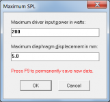
Path length difference, Pmax, Xmax and Filter Wizard input values are now saved to the permanent data record by pressing the F9 function key.
CHANGE 3
In the case of the Filter Wizard, current filter settings can be reset back to the permanently saved settings by pressing the Ctrl+F9 function keys.
To summarise:
1. Press F8 to select the Filter Wizard from the Loudspeaker Wizard.
2. Press F9 to save path length difference, Pmax, Xmax and Filter Wizard input values.
Kind regards,
David
Hi Everyone,
CHANGE 1
The Filter Wizard is now selected from the Loudspeaker Wizard by pressing the F8 function key rather than the F key.
CHANGE 2
Path length difference, Pmax, Xmax and Filter Wizard input values are now saved to the permanent data record by pressing the F9 function key.
CHANGE 3
In the case of the Filter Wizard, current filter settings can be reset back to the permanently saved settings by pressing the Ctrl+F9 function keys.
To summarise:
1. Press F8 to select the Filter Wizard from the Loudspeaker Wizard.
2. Press F9 to save path length difference, Pmax, Xmax and Filter Wizard input values.
Kind regards,
David
Attachments
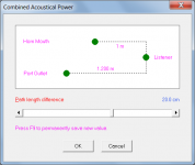
I like the distance diagram. Simple yet useful.
Hi Mark,
As they say, "a picture is worth a thousand words"
") .
.Kind regards,
David
I am building a simple sealed sub and have been considering the effects of firing it into a wall (or base/top plate). I have seen hints that it it possible to model this effect using hornresp but I'm not entirely clear on how to go about it. If this is possible, can anyone provide some guidance on how to do this?
The idea came from this post on another forum which is modelling the effect of a slot. Intuitively this looks like the same effect as firing into a wall but I have never used hornresp before & so am not remotely sure if this is accurate.
My attempt at doing this is based on a 18" driver in a 90L cabinet (which has a 20" face) firing into a wall that is 1,2,3,4" away. Using the method in the linked thread, I therefore calculated
S1 = 1 S2 = 200 Con = 12.7
S1 = 200 S2 = 400 Con = 12.7
i.e.
S2 = the mouth of the slot = the circumference of a circle multiplied by the width of the slot
I used the 20" (~50cm) box width as the diameter of the circle and the distance from the wall as the width of the slot. Therefore a 1" (~2.5cm) distance results in a 2*Pi*(50/2)*2.5 ~= 400
Each Con value is 12.7 (aka 5") as that is half the radius (and the slot is modelled in 2 equal length sections in that linked thread).
Any guidance/help much appreciated!
I am building a simple sealed sub and have been considering the effects of firing it into a wall (or base/top plate). I have seen hints that it it possible to model this effect using hornresp but I'm not entirely clear on how to go about it. If this is possible, can anyone provide some guidance on how to do this?
The idea came from this post on another forum which is modelling the effect of a slot. Intuitively this looks like the same effect as firing into a wall but I have never used hornresp before & so am not remotely sure if this is accurate.
My attempt at doing this is based on a 18" driver in a 90L cabinet (which has a 20" face) firing into a wall that is 1,2,3,4" away. Using the method in the linked thread, I therefore calculated
S1 = 1 S2 = 200 Con = 12.7
S1 = 200 S2 = 400 Con = 12.7
i.e.
S2 = the mouth of the slot = the circumference of a circle multiplied by the width of the slot
I used the 20" (~50cm) box width as the diameter of the circle and the distance from the wall as the width of the slot. Therefore a 1" (~2.5cm) distance results in a 2*Pi*(50/2)*2.5 ~= 400
Each Con value is 12.7 (aka 5") as that is half the radius (and the slot is modelled in 2 equal length sections in that linked thread).
Any guidance/help much appreciated!
Hi, I'm not sure I understand precisely what you are simulating here, perhaps it would help if you attached a screen shot of your hornresp entry screen, but at a first look I would say S1=1cm² doesn't seem right, at least if you have the simulation set to "Nd"
In a different thread the discussion arose how to simulate a port up against a wall, and here's a link to my response how to do it:
http://www.diyaudio.com/forums/mult...-firing-ports-subs-more-less.html#post3571739
(if the direct link doesn't work, it's post number 14 in that thread).
The Method to simulate this for in front of the driver on a sealed box should be fairly similar, just use the surface area of the driver in cm² as Atc, and the volume of the air inside the cone of the driver + the volume of the area of the driver * the distance to the wall as Vtc.
Then set circumference of driver * distance to the wall as S1, and circumference of the box * distance to the wall as S2. L12 should be Par and the distance from the edge of the driver to the edge of the box.
What I say of course assumes a driver in the middle of a circular enclosure wall - for squares or other shapes things will be different. However my gut instinct is that putting the driver up against the wall won't change much for a subwoofer, as long as you leave a moderate amount of distance (circumference of driver*distance to wall > Sd of driver)
OK thanks, I will take a look at the linked thread.Hi, I'm not sure I understand precisely what you are simulating here, perhaps it would help if you attached a screen shot of your hornresp entry screen, but at a first look I would say S1=1cm² doesn't seem right, at least if you have the simulation set to "Nd"
In a different thread the discussion arose how to simulate a port up against a wall, and here's a link to my response how to do it:
http://www.diyaudio.com/forums/mult...-firing-ports-subs-more-less.html#post3571739
(if the direct link doesn't work, it's post number 14 in that thread).
The Method to simulate this for in front of the driver on a sealed box should be fairly similar, just use the surface area of the driver in cm² as Atc, and the volume of the air inside the cone of the driver + the volume of the area of the driver * the distance to the wall as Vtc.
Then set circumference of driver * distance to the wall as S1, and circumference of the box * distance to the wall as S2. L12 should be Par and the distance from the edge of the driver to the edge of the box.
What I say of course assumes a driver in the middle of a circular enclosure wall - for squares or other shapes things will be different. However my gut instinct is that putting the driver up against the wall won't change much for a subwoofer, as long as you leave a moderate amount of distance (circumference of driver*distance to wall > Sd of driver)
Here's what I have so far

I was keeping it simple to begin with by just using the box size for a single driver.
The actual sub I'm thinking of building would have 2 drivers in

in order to squeeze into an alcove like so

This means the actual "slot" would largely be just the space above the sub as it will sit on the floor and the gaps at the sides will be quite narrow.
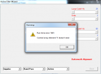
I ran into this while changing the graph type via scroll wheel on the mouse.
Hi Dan,
Many thanks for reporting this problem. The bug was inadvertently introduced in Update 3480-140620 (Post #4606). It has now been fixed.
Hopefully one day Hornresp will work perfectly
.Kind regards,
David
If anything I feel that finding a bug is my tiny contribution to Hornresp.
Hi Dan,
You sell yourself short
.Your ongoing feedback is greatly valued - it is much more than a "tiny contribution", as far as I am concerned.
Kind regards,
David
Hello all,
I tried to run it under Win 7 64 bit and so far no luck. I have seen that others have managed to get it going. Permissions enabled ( under security and third party origin ), all allowances marked, excluded from antivirus, still no luck. Run it in admin mode, my user has all permissions on the notebook. Created a shortcut to see what path it has, its all correct, compatibility tested down to XP Pack 2, but I still get:
Windows cannot access the specified file, path or device. You may not have the appropriate permissions to access the item.
Would appreciate any help.
Last edited:
- Home
- Loudspeakers
- Subwoofers
- Hornresp