No this is the Schematic I have which is the HK versionBoy you guys like to confuse a beginner
Are you saying none of the transistors I have listed will work with the schematic I posted could you pleas just post the part numbers I require for
Q1
Q2
Q3
Q4
Q5
And suggest a good transistor for Q6/7 in place of the 2N types
And if you can do the same for the updated version that uses the BC550C/560C transistor
This will give me Better choices on which one to build I think this will be much easier than talking about comp pairs that are not used but I have taken note of all your posts which will help in understanding the different transistors Valves are must easer
Thanks
Attachments

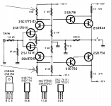
THe tricky thing is to find the JFET pair.
Once you have 2SK170 and 2SJ74,
then there are a number of different you do well with for the other.
First, Q1, Q5, cascoding, is not at all any trouble. Most any TO92 will do.
Power transistors, Q6, Q8, could be MJL3281/1302 or 2SC5200/SA1943.
The reason is that I think those have good gain + low sat (saturation voltage).
Saturation is how much at least voltage a transistor needs to run a specific current.
If we use power transistors that needs high sat voltage, in this amplifier,
we 'steal' away from the only 12V we have to swing with.
Q4, Q2 I see as the critical choice.
They do a very important job, driving the big power transistor.
They should be small transistors that can do well at, say, 10-20 mA.
I would feel better to use BD139/BD140, than to use BC550C/BC560C.
Better also than BC550C/560C is also 2SC2240/2SA970,
if I am correct in that above 5-6mA BC550/560 are not at their best.
At least not as good as 2SC2240/2SA970 when it comes to currents above 10 mA.
My simulations shows an idle current like 9-10 mA for Q2, Q4.
This should be okay for 2SC2240/2SA970, which have low power/heat limit.
There are also TO92 variant of BD139/140 called BC639/640. Specified 1.0 Watt
One weakness with 2SC2240/SA970 is power limit only 300mW.
Otherwise they are fine.
Hope I did not confuse you even more.
This was my thinking.
I am sure there are other fellows that can tell you better.
That know more about and have built.
No this is the Schematic I have which is the HK version
NO read the post
No this is the Schematic I have which is the HK version
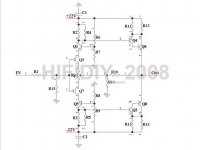
Right I will try again Can you just verify if the following is correct and advice on best ones for Q6/8 thank you pleas don't give number that don't apply to this schematic that just is confusing thank you
Q1 2SC1775
Q2 2SD7567
Q3 2SK170BL
Q4 2SB716
Q5 2SA872
Q6
Q8
Attachments
Hello
Every schematic use the same transistors and JFets. Do not be confused!
I answered to your question in my last post , please read it .
There is no reason to write about Q1 you wrote they don't have (out of spec mean fake)
If you don't get Q1 , U can't use Q5!
For Q3 2SK170 OK only if you get for Q7 2SJ74 and bot have to have the same grade (BL,GR,Y type)
Q2 is a mistake!
Greetings
Hello
I would like to ask for help. I have a need for 2PC 2SC1775 hfE between 400-450.
I have at least 35PC 2SA872 but all has hfE between 400-450.
Also I have some 2SC1775 much higher hfE 500-650.
I would like to buy 2PC 2SC1775 with right hfE or I'm willing to trade with 2SA872.
Guaranteed orig Hitachi part I have and also I would like to get.
Greetings
Mosfet Hiraga Le Monstre
Hello
Here is a schematic for the mosfet Hiraga le Monstre amplifier.
I have a question , to mi it look like the 1R 5W resistor value to high.
Usually with lower value resistor all amplifier tend to sound better . Of course it have to be readjust the current.
My question if I use R47 that would made the amp unstable??
Did someone ever tried to use lower value ?
Thanks")
Greetings gabor
Hello
Here is a schematic for the mosfet Hiraga le Monstre amplifier.
I have a question , to mi it look like the 1R 5W resistor value to high.
Usually with lower value resistor all amplifier tend to sound better . Of course it have to be readjust the current.
My question if I use R47 that would made the amp unstable??
Did someone ever tried to use lower value ?
Thanks
Greetings gabor
Attachments
hello, At last finished the construction so I need to set the bias now.
First of all how to set the 100ohm potentiometer? at the middle point??
I power the le monstre from patteries only, do you know a good bias point so then the batteries go from 13v down to 12v the amplifier will still operate in class-A?
Thanks
First of all how to set the 100ohm potentiometer? at the middle point??
I power the le monstre from patteries only, do you know a good bias point so then the batteries go from 13v down to 12v the amplifier will still operate in class-A?
Thanks
hello, At last finished the construction so I need to set the bias now.
First of all how to set the 100ohm potentiometer? at the middle point??
I power the le monstre from patteries only, do you know a good bias point so then the batteries go from 13v down to 12v the amplifier will still operate in class-A?
Thanks
Hi,
People more knowledgeable will correct me, I hope, if I am wrong, but the 100R pot is to adjust DC offset, not to set bias. When I built this amp I put it in the middle to start and then adjusted it to get DC offset as close to zero as possible.
You could probably adjust the bias by changing the 1R resistors on the output transistors, I guess, but I'm pretty sure the amp will operate in class A at 13v or 12v as it is. (Or did I misunderstand your question?)
Cheers
Nigel
Hello
My first question to you the power supply voltage .. If around 12V and you use GR or BL type JFet better to use 2x1K trim pot instead the 1K resistor .
The 2 piece 1K resistor set up the bias.
To me when I used 12V and BL type JFet 470R was OK to set up the bias around 1A.
That is the reason at first U use 2pc 1K trim pot (variable resistor) And adjust to the half both.
If you need higher bias increase the resistance . If you need lower bias decrease..
The 100R trim pot is for the offset.
After you set up the right bias you can replace the two trim pot..
Greetings
Attachments
Hello
I talk about the total bias one side.
For example you connect the DMM (measure A)between the PS positive and the panel positive.
That the total bias. Usually Hiraga ask for 08A. But if you go higher a bit not a problem .
Be careful when it warm up the bias will increase sometimes 2-300 mA.
My M Hiraga when warmed up I had 1.5A total bias /channel.
I don't know the voltage drop on the 1R 5W resistor .
These way much easier to set up the bias..Hiraga write about the total bias/channel.
When cold 08A..
Greetings
Hello
No I wrote about the orig Hiraga Le Monstre. I used large (oversised) heatsink ,you can go higher in that case.
You gain very little sound wise .Just a bit sound better with the higher bias.
If you set up the amp 08A bias , whe it warm up it will be close to 1A or may be a bit more.
Greetings
No I wrote about the orig Hiraga Le Monstre. I used large (oversised) heatsink ,you can go higher in that case.
You gain very little sound wise .Just a bit sound better with the higher bias.
If you set up the amp 08A bias , whe it warm up it will be close to 1A or may be a bit more.
Greetings
Ok a "simple-silly" question, just to make sure. How to set the correct DC offset with the 100ohm pot? I mean how should I measure the offset?
PS. I set the bias of my le monstre to about 620mA when hot. I have used 1K bias resistors but I found the bias to be very high, about 1.5A. This makes the 1ohm resistors very hot after a few 10s of seconds. I used 1k multiturn trimers in parallel with the 1k resistors and set them to reduce the bias to 0.62A (maybe I will go for 0.5-0.6A later on) and the 1ohm resistors now run cool. It is just a matter of setting the DC offset now so how can I measure this?
PS. I set the bias of my le monstre to about 620mA when hot. I have used 1K bias resistors but I found the bias to be very high, about 1.5A. This makes the 1ohm resistors very hot after a few 10s of seconds. I used 1k multiturn trimers in parallel with the 1k resistors and set them to reduce the bias to 0.62A (maybe I will go for 0.5-0.6A later on) and the 1ohm resistors now run cool. It is just a matter of setting the DC offset now so how can I measure this?
Hello
Just use the trim pot for the place of the 1K resistors! That way easier to know the final value for the 1K resistors.
After you set up the correct bias(total bias) between the PS and each panel measure both trim pot and replace it with the same or the closest value resistor.
Do not measure any bias on the 1R 5W resistor! That does not give you correct measurement. If you have 1A total bias/ channel after warm up the 5W resistor will be hot but not to hot! Depend on the resistor quality.
Yes the offset you measure these way. Set up your DMM on DCV and measure the speaker terminal .
Be careful do not short (connect the speaker terminal) because you will burn your amp.
If you measure DC Voltage that is OK , that will not short the amp!
If you do not understand clearly something please ask.
Sometimes not possible to keep the offset close to 0V. In that case you have to change one of the JFet higher or lower IDSS..
These all depend how close was matched all the semis.
Do not be afraid the amp still will function right..Is good to have the max offset all the time under 0,5DCV..
But better to close to 0V , or as close as possible.
If your 5W resistor still to hot to keep your finger on at least 5-10 sec, please use hot glue and a small piece of heat sink , glued on . In that case on both resistor! That will keep coll-er the 5W resistor. U need just a small piece of heat sink there. Otherwise it will look to ugly.
That gave to the amp more stability. You know the amp bias moves how the parts & (heat sink) warms up.
Sometimes less bias move up & done give you less trouble with the offset. If you get one side 470R and another side 500R at the place of the 1K resistor and 0V offset please use those values to replace the trim pot.
Make sure when you do something (solder, or connect the DMM to measure the bias) in the amp the power in the PS capacitors close to 0Volt. Turn of the amp always!
If take to long time to get 0V you can short it with a 40W light bulb. The ground and the positive PS after the ground and the negative ..
Greetings
Thank you for the information.
Ok just to confirm:
To set the offset, leave the speaker connected to the amplifier, the amplifier switched on and measure the voltage between the positive speaker terminal and the ground. A correct offset should read as close as zero volts, right?
(does the offset change during the bias setting?)
I use non inductive 1ohm 4W resistors and they do not get hot (you can easily touch them and just feel a little heat) when the voltage drop across them is set under 1V. Why measuring the voltage drop across them does not mean that the bias is correctly set, could you please explain this, as other members seem to agree on this?
And finally, when is the amplifier operating "more on class-A"? when the idle current is set to higher amperage or to lower (i.e higher voltage drop across the 1ohm resistors or lower)?
.... Why measuring the voltage drop across them does not mean that the bias is correctly set, could you please explain this......
I'm curious too
Hello
Of course you measure voltage drop on the 1R 5W resistor, that is why called resistor .
I wrote leave the 5W resistor alone, you can not get clear bias picture. Just after the right bias set up and warm up you can can measure the voltage drop on the 1R 5W resistor..Connect your DMM between the PS positive and one of the panel positive .
Leaved there for 1 hour and you will get clear picture what is going on.
When the amp cold the bias is low. If you have the right size heat sink it will warm up slowly (probably take 30 or 60 minutes) to reach the total warm up.
You can hook up your speaker meanwhile you do these and you can listen music to.
When the amp cold you set up the bias 0.8A , after warm up it will be around 1-1.1A...
If you do not do at these way you will never know what is your bias when the amp when cold or what happen doing warm up.
If you done with one channel please repeat on the another channel.
When you done leave the amp to run a couple weeks after you can measure it again. If you need to readjust because is to high or to low you can do it with the 2 trim pot you use at the place of the 2piece 1K resistor.
Unfortunately MHiraga bias move with the warm up!
If you like the bias replace the the 2 trim pot with resistors , of course the same value you measure on each trim pot.
Work only on one channel at the time!
Greeting
- Home
- Amplifiers
- Solid State
- Hiraga "Le Monstre"