coming back?
Hi,
no, i`m not coming back from digital amps to class A.
in the moment i drive my speakers active with some class T amps, which are battery driven. I am very satisfied.
But: Since i am a little bit bored and have some time and some Heatsinks and Toroids left.... i need something to tinker...
best, Ralf
Hi Ralf!
Nice to see you again!
Are you coming back from the Digital and Class D world?!?
I think the best would be if you would try the Profet amplifier!
I can't answer to this question. It is on your taste. The F5 will sound different because the Mosfets.
Greets:
Tyimo
Hi,
no, i`m not coming back from digital amps to class A.
in the moment i drive my speakers active with some class T amps, which are battery driven. I am very satisfied.
But: Since i am a little bit bored and have some time and some Heatsinks and Toroids left.... i need something to tinker...
best, Ralf
Hi Ralf!
")
Greets:
Tyimo
You are incorrigible.in the moment i drive my speakers active with some class T amps, which are battery driven. I am very satisfied.
Greets:
Tyimo
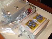
At last,
I found the time to begin the assembly of the amplifier..
This is how it can be squized if you use higher wattage resistors
(only the shincohs have been soldered)
Hi Neazoi !!!!
WHoa they are soem serious resistors ! what wattage shinkohs are they
lol i think they are a bit extreme for the currents involved - but you will have good thermal stability
-Dan
Hi Ralf!
You are incorrigible.
..that isnt true.
If i found a amp, which is definately better (im my chain and personal taste) i would change to class a or whatever.
but at the moment my modified Tripath based amps 2021b, 2024 (Glimmer, Wima FKP1, Elna Cerafine) and with the buffered batteries , it`s an unbeatable chain for very less money!
High sensible speakers are a must - with 85db speakers my T-Amps have not enough power for driving them to real high volumes.
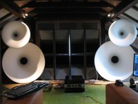
Here are my speakers:
the big Tapped Horns can not be seen here
best,
Ralf
Attachments
Hi Neazoi !!!!
WHoa they are soem serious resistors ! what wattage shinkohs are they
lol i think they are a bit extreme for the currents involved - but you will have good thermal stability
-Dan
Yes they are much more wattage than they needed.
Unfortunatelly this wattage is the only one I could found in the values needed (shinkohs are very rare as you know). But it does not harm and may be even greated (thermal stability) like you said.
I tried to keep the leads as short as possible (0.5cm more has not inductive effect in sound frequencies)
The big ones are 2watt. They are bigger in size than the standard 2watt carbon ones.
They are very expensive, much more than caddocks
For this amplifier I will use non-standard ideas. I design my whole audio system from scratch with a different philosophy. I will give some hints and comments are welcome.
For example, to minimize the capacitance of the input cables I will not use coaxials. I will use separate plain silver wire for each +/- (which is much lower cost than silver coaxial) and some audio note non magnetic speaker posts and bananas for the outputs as well for the inputs! For the output cables also I will use the same idea but using thicker silver wires. These silver wires are sold much much more cheaply on ebay and they are 99% or more plain silver. No shunt capacitance that way (minimized), perfect characteristics.
The drawbacks
You have to make all your sources compatible to this non-RCA plugs
No shielding. But the room is far from electromagnetic sources and it is at underground level
(the earth around the room is the best shielding. proof that my mobile phone is dead when inside the room)
For the preamplifier I will use a passive one (of course) but using new ideas too. My CD and MD have internal attenuators, there is no need for an additional (noisy) volume control. For the Phono section I am thinking of using a kind of lightspeed attenuator (this idea is brilliand but I do not know about the sonic properties of the photo resistors)
I will definitely want to make an autobias circuit for the monstre too. I will work on it...
And of course no crossovers on speaker cones (I use a pair of nirvana super8)
Sorry if I am a bit out of topic, but starting from this nice direct coupled cuttie it is worth starting to think of cable or components issues. After all you have to know how what I/O connectors you are going to use when builting it.
Any comments are welcome
I will post some more photos soon!
Last edited:
Ralf, Put simply I am jealous of your speakers and i have elsinores...
Neazoi, I like your ideas with the cable capacitance/inductance reduction, wheni was testing recently i was using a MSO capable of very high sample rates and over 1GHz. the three minor problems i encountered were
1, Inductive load resistor >6uH
2, cable impedance on the input and its reactive properties
3, the signal generator / signal input cable i was using seemed to limit the amplifiers freq response.
also - my personal opinion is you will not need to adjust the bias point once you have it at the right value this is a very stable amplifier, i think modifying the bias circuit is probably unnecessary - but let us know if you do try it out.
-Dan
also - my personal opinion is you will not need to adjust the bias point once you have it at the right value this is a very stable amplifier, i think modifying the bias circuit is probably unnecessary - but let us know if you do try it out.
-Dan
Dan the problem is that I am using battery-only operation so the batteries will get discharged about 1-1.5v before they need to be charged again. This voltage drop will vary the bias of the amplifier so a bias "compensation" circuit must be made i think?
This is not the same as temperature (thermal) autobias. This is voltage (accross the 1ohm resistors) autobias.
Neazoi,
The bias will not vary by a large amount (from what i saw when testing)
I wish I recorded the exact change values down now
I can let you know when i fire it up again if you like
-Dan
Yes it would be an interesting point.
The voltage of the batteries will fall from 13.4v to 12v, not less
If the bias keeps the amplifier still in class-A within these limits, then a compensation circuit may not be needed,
it was definately in class A
if you set the bias for 0.6A at 13.5V then it would be more like 0.5A at 12V
actually i am thinking of getting 2 50Ah lead acid batteries (car batteries)
for the le monstre... I just want to test it with a power supply first to see what its like and iron out and little glitches
-Dan
if you set the bias for 0.6A at 13.5V then it would be more like 0.5A at 12V
actually i am thinking of getting 2 50Ah lead acid batteries (car batteries)
for the le monstre... I just want to test it with a power supply first to see what its like
and iron out and little glitches-Dan
it was definately in class A
if you set the bias for 0.6A at 13.5V then it would be more like 0.5A at 12V
actually i am thinking of getting 2 50Ah lead acid batteries (car batteries)
for the le monstre... I just want to test it with a power supply first to see what its like
-Dan
I will have this bias setting in mind. If the difference is so small then the compensation circuit is not needed. (nice)
A warning about the NON Deep cycle lead acid car batteries, they can be damaged much more easily than deep cycle ones if they are deep discharged.
Car batteries are MUCH cheaper though. In Greece you can find one for 50Euros or so, where as deep cycle ones are about double the price.
yes... I would love to buy some deep cycle lead acid batteries.
but car batteries here are about $100 or less if you get a good deal.
deep cycle in a 40+ Ah size are very expensive more than three times.
although i would prefer Sealed lead acid deep cycle... i have no problem making a charger/power supply which will keep them in good condition.
my plan is to make a voltage regulator based supply with a very basic transistor based switch on a relay.
so it runs on batteries until it hits 12V and then the supply charges back up and then turns off - what do you think ?
-Dan
yes... I would love to buy some deep cycle lead acid batteries.
but car batteries here are about $100 or less if you get a good deal.
deep cycle in a 40+ Ah size are very expensive more than three times.
although i would prefer Sealed lead acid deep cycle... i have no problem making a charger/power supply which will keep them in good condition.
my plan is to make a voltage regulator based supply with a very basic transistor based switch on a relay.
so it runs on batteries until it hits 12V and then the supply charges back up and then turns off - what do you think ?
-Dan
It sounds ok to me. Even for the deep cycle batteries the manufacturer suggests not to discharge them less than 12v to last more.
Be aware of this "live" switching of the charger though. You may want to think to have a mute circuit to mute the music just before switching on the charger and then un-mute it a little bit after the charger is connected. But you have to test if this is necessary. Also you have to think of how you would charge the batteries, as they are in series. you cannot charge them one at a time.
In my implementation I use a double switch and when I want to charge the batteries, the amplifier is always stay off. also I am not charging the batteries because this was not recommended by the manufacturer, so another switch selects which battery should be charged each time (twice the time to charge both but a smaller charger needed)
My batteries are 80Ah so they take more to charge.
Another thing you ave to think of is that the charger may be quite noisy (some of them ar switching mode chargers) and this will have an effect in sound, so I do not know if this is a good idea to connect the charget at the time you listen to the music. If you want this, then maybe you should not go for a charger but for the hybrid hiragas approach.
In my setup I do not care about charger noise because when I charge the batteries, the amplifier is switched off.
totally agree i plan to use a normal linear regulated supply the same supply which can run the amp to charge the batteries. the other option i thought was put a voltage display on the amp and just use the manual method.
I do have the original charging circuit somewhere...
-Dan
I do have the original charging circuit somewhere...
-Dan
totally agree i plan to use a normal linear regulated supply the same supply which can run the amp to charge the batteries. the other option i thought was put a voltage display on the amp and just use the manual method.
I do have the original charging circuit somewhere...
-Dan
The collected info, including the circuit you are looking for can be found in my audio page at Audio Constructions
check the le monstre under projects
As bobodioulasso stated, a good technique would be to have the batteries charged when the amplifier is switched off. Using an automatic charger can compensate for over charging and battery maintenance, to keep the battery always fresh.
Then a simple circuit to switch off the amplifier when the voltage goes below 12v could be desirable! this can be made even more clever, by warn the user a few minutes before the voltage gets to 12v. (we do not like if the music cutts off rapidly)
Then a simple circuit to switch off the amplifier when the voltage goes below 12v could be desirable! this can be made even more clever, by warn the user a few minutes before the voltage gets to 12v. (we do not like if the music cutts off rapidly)
the switching off to charge idea even better !
another thing i did some rough calculations...
say the battery is 80Ah@12V that is 960Wh per battery total 1920Wh
the amp draws a continous (maximum) 12 watts or so for a stereo pair 24W
the run time is more than i expected originally..
maybe more like 40h ?!??!??!?!?!
not sure if this is accurate depending on the discharge curve of the battery
-Dan
- Home
- Amplifiers
- Solid State
- Hiraga "Le Monstre"