Hi Upupa,
Here is my new layout arrangement. all outputs had been pushed up and input down. VDD and VEE have less spreading but need a jumper to connect the feedback resistor ground and input ground cos' can't find a way to make a short path between them What do you think of this new layout? Will it still hum?
What do you think if I fill all unrouted area with copper and connect it to PSU ground?
Regards,
Ipanema
Here is my new layout arrangement. all outputs had been pushed up and input down. VDD and VEE have less spreading but need a jumper to connect the feedback resistor ground and input ground cos' can't find a way to make a short path between them
What do you think of this new layout? Will it still hum? What do you think if I fill all unrouted area with copper and connect it to PSU ground?
Regards,
Ipanema
Attachments
Hi!
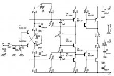
Here is the schematic of the BJT input version.
Due to the smaller output impedance (1.3Ohm) of this version, the bass is less with my speakers, that is the main reason I preferred the FET version. I have to admit that I did not make extensive listening tests to compare the FET and BJT input version, so there can be more difference in sound.
Attachments
Me too have lot of difficult to find some replacement for original Hiraga amplifier. In particular th hig gm input fet that are critical for results seems impossible to find.
Here my list of equivalent (first item of each group is the original one). Any suggestion on equivalent?
POWER NPN 50V 7A 60W 15MHz 2SD844 TOSHIBA
POWER NPN 50V 7A 60W 15MHz 2SD1063 TOSHIBA
POWER NPN 50V 7A 60W 15MHz TIP35A ST
MEDIUM PNP 2SB716 TOSHIBA
MEDIUM PNP ~MJE350 ON SEMI
SIGNAL NPN 2SC1775E TOSHIBA
SIGNAL NPN ??
JFET NCH 2SK170Y TOSHIBA
JFET NCH 2SK364 TOSHIBA
SIGNAL PNP 2SA872E TOSHIBA
SIGNAL PNP ??
JFET PCH 2SJ74Y TOSHIBA
JFET PCH ??
MEDIUM NPN 2SD756
MEDIUM NPN ~MJE3440 ON SEMI
MEDIUM NPN 2SC2632 TOSHIBA
POWER PNP 2SB754
POWER PNP TIP36A ST
Sorry, I realized that there is a 3D more pertinent, devoted only to the Monster. I moved the post here:
http://www.diyaudio.com/forums/showthread.php?postid=714698#post714698
http://www.diyaudio.com/forums/showthread.php?postid=714698#post714698
atot said:Hi!
Here is the schematic of the BJT input version.
here is my implementation of the BJT version, with MOSFET at the output.
What I found is that you can bias this thing into class B. However cross over distortion starts to creep up when bias goes below 350ma (you can go lower with a bjt at the output).
I would say 750ma and up is better.
R5/R8 are trimmers for biasing and output DC adjustment. R10/R7 and R9/R6 for gain, R14/15 can be omitted or dialed up to 10k if you use BJTs at output.
Attachments
components
Ipanema, can you give more details on what components on the board you used? I guess bc550/560 on all other places except the output transistors. Please also specify the brand of the transistors if available. And what make of resistors etc? I'm trying to get the optimum out of my monstre and have tried many many component changes but it is not to my taste yet, so maybe your info will help.
Ipanema, can you give more details on what components on the board you used? I guess bc550/560 on all other places except the output transistors. Please also specify the brand of the transistors if available. And what make of resistors etc? I'm trying to get the optimum out of my monstre and have tried many many component changes but it is not to my taste yet, so maybe your info will help.
Hi rmqvs,
The schematic can be found here. http://web.vip.hr/pcb-design.vip/hiraga.html Scroll down to look for the new transistor version.
I substitute TIP3055/2955 with MJ4302/3281. Also swap 170/109 with 246/103 with no difference detected. Any comment? I can send you PCB drawing if you need one. This is my first PCB drawing, which Upupa have been kind enough to guide me through.
other question
Thanks Ipanema,
I know the circuit, that's okay. I more precisely want to know of what brand you use the transistors (3055 Philips or Motorola, bc550 philips or without any brand name on it, type b or c). What is printed on them, maybe some close up pictures help also. Besides that if possible more details about what brand of resistors you use (holco, beyschlag, philips, dale or unknown).
Thanks.
I use 550C/560C, better hfe but could do with any 550/560. MJ3281/4302 are from Onsemi. All resistors are metal film. Just build it and play around with the components. Maybe I got a bad ears that I can't hear much difference between different components. BTW, I prefer to build chipamp than class A amp. Just can't manage to get those bulky heatsink. Good luck!
Ipanema,
comparing original circuit and your Hiraga version, it seems, that your circuit has 20dB less loop gain. Just compare the values of offset trimmer and first stage collector resistor. You have 470R to 390R, and the original was 100R to 1k.
With less open loop gain, you have less feedback, higher output impedance and your damping factor goes down. I think your output impedance is now in the region of 4 Ohms (it is 0.5 Ohms for the original version). High output impedance -> less controlled bass -> etc ...
best regards,
Hartmut
Hi HifiDaddy,
The open loop gain is probably lower than the original but surprisingly the bass is really good compared to the latest JLH variation. Do you know why it is so?
BTW, do you have the spice model for 2Sk170/2Sj109 and 2SK246/2Sj103? I would like to verify this with simulation.
Thanks.
The open loop gain is probably lower than the original but surprisingly the bass is really good compared to the latest JLH variation. Do you know why it is so?
BTW, do you have the spice model for 2Sk170/2Sj109 and 2SK246/2Sj103? I would like to verify this with simulation.
Thanks.
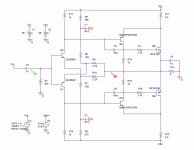
I've used Sanken 2sc3855/2sa1491 at outputs. Sounded better to my ears than tip2955/tip3055
This is with 2sk146/2sj103/bc550/bc560
my new pcb (not tested yet)
http://i29.photobucket.com/albums/c272/aqvrs1853/lemonstretransparent.jpg
http://i29.photobucket.com/albums/c272/aqvrs1853/lemonstrepcb.jpg
PCB needs one wire from 10ohms/220 ohms resistors to 470 ohms pot.
pls comment
Greetings,
Klaas
JohanH said:Joris,
Thanks for the input.
Yes I know this is dangerous and highly subjective. The reason I chose tantalums as one of the options is indeed that Hiraga had them in their catalogue for Monstre parts. Your Post (and the cost-difference (I am dutch too)) makes me want to try the Kiwames first.
Do you know if triodes.nl sells other values thans they list as well?
Johan
Hiraga had an article on the distortion of the resistors, the tantalums going down to -120 dB. Well, as soon as you bend & solder one (300 degrees is like inferno), its gone, that low level of distortion - I expect.
I have a batch of tin-oxide on glass resistors, hardly predictable, too. That is why I figured out the previous explanation.
HI
I have all the jets and all the original transistors for the Le Monstre .
If you are intrested please let me know .
Regards
I have all the jets and all the original transistors for the Le Monstre .
If you are intrested please let me know .
Regards
Ipanema said:Hi Atot,
Where can I source 2sj74? Can't find any in malaysia. What is your output trasnsistor biasing?
What other components did you change from the orginal?
Regards,
Ipanema
- Status
- This old topic is closed. If you want to reopen this topic, contact a moderator using the "Report Post" button.
- Home
- Amplifiers
- Solid State
- Hiraga 30W vs. Le Monstre