The reason can be the FETs.
The 2SK246/2SJ103 are low transconductance devices, while the original 2SK170/2SJ74 are high (4 mS vs. 20 mS or so). Thus the output impedance of the modified amplifier is about 20 Ohms, while the original one has near 4 Ohms. The 20 Ohms is very high, it will alter the frequency response of the loudspeaker considerably, the impedance curve determines it mainly.
The other parts are OK, just the input FETs should remain the original.
ati
Hi,
I built a preamp based on opa2134 with gain of 20x. Now only the Monstre willing to open its mouth to sing!
Funny, the Monstre supposed to have gain of 20x, is this not enough?
Another note, I changed the bias resistor from 390ohms to 470ohms. output bias changed from 240mA to 450mA. How to calculate ouput power based on these data?
Regards,
Ipanema
Hi Ipanema,
Actually the gain is 23x, but if you have 20 Ohms output impedance you only get 6/26=0.23 amplitude in the case of 6Ohm speaker impedance. So the total gain is about 4.6x, while the usual gain of commercial amplifiers is ~30x, this 16dB difference is quite big.
With 0.45A the amplifier has the same output power with lower bias current, but will enter into class B at around
0.9x0.9*6=4.8Watt power.
ati
PS: Try to measure the output signal amplitude at around 500Hz with and without load (4-8 Ohms), you will notice a huge amplitude drop with load.
I used the Ltspice simulation, and built the Le Monstre amplifier with different transconductance input Fet pairs. The simulation and the measured values were agreed: the 2N3819/20 pair gave 20 Ohm and the 2sk170/sj74 3.8 Ohm output impedance.
The 2sk246/sj103 gave the same output impedance in the simulation as the 2N3819/20, because they have similar transconductance. The open loop gain is higher with higher input jfet transconductance, and the feedback is higher this way which decreases the output impedance.
ati
Currently I am listening to the 2sk170/sj74 version of the Le Monstre. No case yet, the boards are lying around the floor.
Attachments
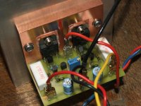
The FETs also impossible to obtain here also, that was my problem at the beginning, so I built it with another FETs. The result was promising so I built it with bipolars at the input (needs redesigning), but I preferred the FETs. Fortunatelly at my work we have Japanese partners, so I asked a favor and they sent me 6-6 each.
You may want to search the diyaudio.com site for possible sources of the FETs.
You can see the components on the attached picture, with ~9mA Idss FETs the idling current is about 700mA.
Regards,
ati
You may want to search the diyaudio.com site for possible sources of the FETs.
You can see the components on the attached picture, with ~9mA Idss FETs the idling current is about 700mA.
Regards,
ati
Attachments
I use LTspice/SwitcherCAD from National Semiconductor and found the models on diyaudio.com forums. Just make a search with spice and 2sj74 keywords for example.
The LTspice/SWCAD software:
www.linear.com/designtools/softwareRegistration.jsp
If you do not want to register just select the link at the bottom.
ati
The LTspice/SWCAD software:
www.linear.com/designtools/softwareRegistration.jsp
If you do not want to register just select the link at the bottom.
ati
PCB relayout
Hi Upupa,
I build the Monstre with my previous PCB layout. You are correct, it hums even though I had break the loop.
Here I have relayout according to your suggestions. Pls advise if there is any wrong with the layout. i'm using Eagle demo version, which I can't find the library for 2sk170/2sj74, so I just use BC550/BC560 instead since they have the same pin configuration. I'm also adding 100uF for the 2K voltage divider and 1000uF on board PSU filter.
Pls advise.
Thanks
Attachments
Schematic
Hi Upupa,
Here's the schematic that I draw. The actual schematic can be found at http://web.vip.hr/pcb-design.vip/hiraga.html
Thanks.
Hi Upupa,
Here's the schematic that I draw. The actual schematic can be found at http://web.vip.hr/pcb-design.vip/hiraga.html
Thanks.
No, I don't like it . Make at one side of PCB inputs terminals and at oposite side all others, including terminals for power transistors. All devices ( including 1 R's and output terminals ) must be at PCB. Make ALL terminals screwed. So go on, you must make much better PCB than original .
. Make at one side of PCB inputs terminals and at oposite side all others, including terminals for power transistors. All devices ( including 1 R's and output terminals ) must be at PCB. Make ALL terminals screwed. So go on, you must make much better PCB than original .- Status
- This old topic is closed. If you want to reopen this topic, contact a moderator using the "Report Post" button.
- Home
- Amplifiers
- Solid State
- Hiraga 30W vs. Le Monstre