One with original NEC transistors and teflon boards and holco resistors on sale :
Hiraga 20W Class A Power AMP Board KIT | eBay
Nice price
I would not invest $200 into that set, not even half of that.
I did tested my Hiraga with the original NEC transistors and ON semi modern transistors outperformed the NEC by a great margin. I made A-B test and the difference was very clear, so I sold my NEC power transistors and drives.
Those NEC semis were 100% originals!!
I sold them on Ebay for $50 with the drivers together.

Hiraga need great power supply with good quality caps! One who build these amp must invest $$$ into the PS. I think half the price must be invested into the PS out of the total cost including the amplifier case. Even that price have to be invested smart.
Also I would not build the one (version) which has the 13V diode at front.
These one is much better.
That is my experience
I do not want to argue over ..Attachments
Hi.
The time of NEC ended.
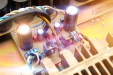
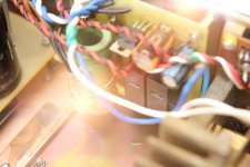
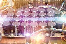
Now I making Hiraga's 20W (1979), with 0,858F (26*33000uF Yageo LG) in filter and 2*6800uF (Nichicon KW) on each channel, beside stabilitrons - 1500uF Panasonic FR.
http://www.diyaudio.com/forums/solid-state/193-hiraga-20w-class-94.html#post4542975
To me MJ15024 & 25 from ON semi power transistors with MJE15031 & 32 drivers gave the best performance.
Had better, deeper bass (more weight) and very well controlled, the mid range was much cleaner the vocals very good
The NEC set gave me warmer sound a bit tube like but the mid area was a bit muddy, les bass and not as controlled. All together sounded a bit flat.
I would chose the ON semi always over the NEC.
I tested the NEC drivers with the ON semi power transistor I did not like the result.
Also I tested with two different type of Toshiba I did not like those either
I did tested MJ11003 & 11004 ON semi power transistors to it was closer to the other ON semi than the NEC. Still not as good as the 11024 &25.
Now I will test the MJL4281 and complementary also I have original Toshiba Green and black transistors. These PC board was designed for these plastic type of transistors.
If the metal can MJ11024/25 will be better will use some short wires to connect to these PC board. I would chose higher voltage caps than 25V(based on my experience)
My toroid is 500VA (for both channel)and get warm after couple hours some people use 300VA only.........
Again the PS is the heart of these amp.
Hi, very big thanx for info.To me MJ15024 & 25 from ON semi power transistors with MJE15031 & 32 drivers gave the best performance.
Had better, deeper bass (more weight) and very well controlled, the mid range was much cleaner the vocals very good
The NEC set gave me warmer sound a bit tube like but the mid area was a bit muddy, les bass and not as controlled. All together sounded a bit flat.
I would chose the ON semi always over the NEC.
I tested the NEC drivers with the ON semi power transistor I did not like the result.
Also I tested with two different type of Toshiba I did not like those either
I did tested MJ11003 & 11004 ON semi power transistors to it was closer to the other ON semi than the NEC. Still not as good as the 11024 &25.
Now I will test the MJL4281 and complementary also I have original Toshiba Green and black transistors. These PC board was designed for these plastic type of transistors.
If the metal can MJ11024/25 will be better will use some short wires to connect to these PC board. I would chose higher voltage caps than 25V(based on my experience)
My toroid is 500VA (for both channel)and get warm after couple hours some people use 300VA only.........
Again the PS is the heart of these amp.
Wires will be 7 cm length with 1.5 millimeter square cross section.
+-19VDC after CRC and bias 1,35A.
Nice price
I would not invest $200 into that set, not even half of that.
I did tested my Hiraga with the original NEC transistors and ON semi modern transistors outperformed the NEC by a great margin. I made A-B test and the difference was very clear, so I sold my NEC power transistors and drives.
Those NEC semis were 100% originals!!
I sold them on Ebay for $50 with the drivers together.
Hiraga need great power supply with good quality caps! One who build these amp must invest $$$ into the PS. I think half the price must be invested into the PS out of the total cost including the amplifier case. Even that price have to be invested smart.
Also I would not build the one (version) which has the 13V diode at front.
These one is much better.
That is my experience
Nice inputt about the output transistors. It's a serious information as J Hiraga spended some times to choose it... and even more with some like the Némésis or Le Monstre !
Hi, very big thanx for info.
Wires will be 7 cm length with 1.5 millimeter square cross section.
+-19VDC after CRC and bias 1,35A.
7Cm long wire with that thickness must be OK
The caps will survive +-19VDC but to be honest I do not like them.
I hocked up 10PC Nippon CC 33 000uF 25V to a Class A amplifier +-16VDC rail voltage
Compare to the 4PC Mepco 50 000uF or 4PC Mallory 62 000uF CRC the result was a disaster
Also I got 4PC Philips (good quality) 60 000uF 25V and to me useless, I do not like the result. My opinion because the low voltage..
I only purchased those low Voltage caps because they were cheap and the shipping (local) also was cheap. To me the big can industrial or audio caps come first in amps like Hiraga. I think is not a accident Hiraga uses those giant caps and higher voltage in the orig. PS. Now I do not want to upset you! Please tested very well those caps and give some time to burn in but if you have some Mepco, Mallory or CDD etc. min. 35V please compare with that.
I purchase on the Ebay 2PC Panasonic giant caps very close to 1F each but only 30V if I remember well. I did not tested those yet I hope they will be not to bad. I spent a fortune on those two capacitor. A lot of people bid on it because those can be used in car audio..
Again take a look the Krell amplifier or some other big name the pick those giant caps also. Again I do not say your cap bank can not be good please tested very well. Mr. Pass in his amps uses smaller size caps
(higher voltage)... Hardly wait on your first impression. I also used small size Nippon CC 8PC 10 000uF KMH type (brown sleeve) 63V they are they good Again I only share my experience, someone may have different so I do not want to open a topic on these.
Other people experience can help us, so my motivation based on that only.
Can you share with us all the transistors you will use in your amp.
I still have some 10 or 20 pair original 2SA872A & 2SC1775A hard to find them but can be replaced with other type Like BC550C BC650C or so.. I never tried other type on the front because I know the 2SA872A & 2SC1775A are good and was very popular for a reason.
Hardly wait on your impression.
Last edited:
7Cm long with that thickness must be OK
The caps will survive +-19VDC but to be honest I do not like them.
I hock up 10PC Nippon CC 33 000uF 25V to a Class A amplifier +-16VDC rail voltage
Compare to the 4PC Mepco 50 000uF or 4PC Mallory 62 000uF CRC the result was a disaster
Also I got 4PC Philips (good quality) 60 000uF 25V and to me useless, I do not like the result.
I only purchased those low Voltage caps because they were cheap and the shipping (local) also was cheap to. To me the big can industrial or audio caps come first. I think is not a accident Hiraga uses those giant caps and higher voltage in the orig. PS. Now I do not want to upset you! Please tested very well those caps and give some time to burn in but if you have some Mepco, Mallory or CDD etc. min35V please compare with that.
I purchase on the Ebay 2PC Panasonic giant caps very close to 1F each but only 30V if I remember well. I did not tested those yet I hope they will be not to bad. I spent a fortune on those two capacitor. A lot of people bid on it because those can be used in car audio..
Again take a look the Krell amplifier or some other big name the pick those giant caps also. Again I do not say your cap bank can not be good please tested very well. Mr. Pass in his amps uses smaller size caps
Again I only share my experience, someone may have different so I do not want to open a topic on these.
Other people experience can help us, so my motivation based on that only.
Can you share with us all the transistors you will use in your amp.
I still have some 10 or 20 pair original 2SA872A & 2SC1775A hard to find them but can be replaced with other type Like BC550C BC650C or so.. I never tried other type on the front because I know the 2SA872A & 2SC1775A are good and was very popular for a reason.
Hardly wait on your impression.
As I said before - BC5xx series not good variant for this amp (And doesn't matter - fairchild, nxp or on semiconductors).
About caps - I think good result could be with KEMET PEH200 caps.
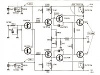
Jean Hiraga's Class A 20W Amplifier (L'Audiophile. April, 1980).
Attachments
hi friends,
i need help in building power supply for the 30W Hiraga Monoblock amp.
my toroidal is going to be 400VA 24V ones and i can provide a maximum of 0.5 Farad [18X0.033F, 35V cap bank] of capacitance for the PSU.
-----L
___^^^^___
|...................|
=C1..............= C2
|...................|
i read that the CLC power supply filter is better than CRC in smoothing the DC. but i did not come across many examples of a CLC filter. what would be the Inductor value that might be sufficient for above requirement.
1. i read on one of the threads that anything above 2mH should be fine. can somebody help me in deciding these values?
2. i read that C1 would see a lot ripple as it faces the raw DC first, should I use different caps [better rating?] for C1? if it is not too much of an issue, i would like stick to same caps [they are expensive!! ]
this is what i am planning to do
L=2.5mH
C1=0.15F and
C2=0.35F
i need help in building power supply for the 30W Hiraga Monoblock amp.
my toroidal is going to be 400VA 24V ones and i can provide a maximum of 0.5 Farad [18X0.033F, 35V cap bank] of capacitance for the PSU.
-----L
___^^^^___
|...................|
=C1..............= C2
|...................|
i read that the CLC power supply filter is better than CRC in smoothing the DC. but i did not come across many examples of a CLC filter. what would be the Inductor value that might be sufficient for above requirement.
1. i read on one of the threads that anything above 2mH should be fine. can somebody help me in deciding these values?
2. i read that C1 would see a lot ripple as it faces the raw DC first, should I use different caps [better rating?] for C1? if it is not too much of an issue, i would like stick to same caps [they are expensive!!
]this is what i am planning to do
L=2.5mH
C1=0.15F and
C2=0.35F
Last edited:
Jean Hiraga's Class A 20W Amplifier (L'Audiophile. April, 1980).
Hi
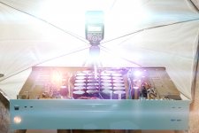
The size of your heatsink is enough? I used much bigger open style and was very very hot!
Be careful no to cook the power transistors.How do you like the result..
Are you satisfied?
Greetings
Hi
The size of your heatsink is enough? I used much bigger open style and was very very hot!
How do you like the result..
Are you satisfied?
Greetings
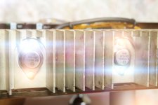
ohhh yeah - very very very ultra hot.

+-19VDC, bias 1,25A, after 3 hour idle - +47C.
Hi
The size of your heatsink is enough? I used much bigger open style and was very very hot!
How do you like the result..
Are you satisfied?
Greetings
Very good resault: the sound is clear, light and soft.
What value of R would you fit into an rCRC filter?hi friends,
i need help in building power supply for the 30W Hiraga Monoblock amp.
my toroidal is going to be 400VA 24V ones and i can provide a maximum of 0.5 Farad [18X0.033F, 35V cap bank] of capacitance for the PSU.
-----L
___^^^^___
|...................|
=C1..............= C2
|...................|
i read that the CLC power supply filter is better than CRC in smoothing the DC. but i did not come across many examples of a CLC filter. what would be the Inductor value that might be sufficient for above requirement.
1. i read on one of the threads that anything above 2mH should be fine. can somebody help me in deciding these values?
2. i read that C1 would see a lot ripple as it faces the raw DC first, should I use different caps [better rating?] for C1? if it is not too much of an issue, i would like stick to same caps [they are expensive!!
this is what i am planning to do
L=2.5mH
C1=0.15F and
C2=0.35F
That first r is the resistances in the circuit inherent in the wiring, rectifier, transformer secondary and reflected primary.
Without these resistances the first C cannot work as a filter. It just stores the charge.
Convert the R to an R+L where R is the resistance of the air-cored inductor.
10 Turns will attenuate the highest interference frequencies.
30Turns will attenuate a decade lower. 100Turns will attenuate 2decades lower.
I just wound 100Turns on a 15mm bobbin with 10mm between the temporary cheeks and then looked at the change in shape of the sawtooth waveform on the scope.
It was clear that much of the vhf was being attenuated.
In the end I decided that 150Turns was as far as I wanted to go. That 150Turns had ~ 0r6 to 0r7 of resistance. That's why I wrote R+L earlier.
I end up with an rC{R+L}CC filter.
What value of R would you fit into an rCRC filter?
That first r is the resistances in the circuit inherent in the wiring, rectifier, transformer secondary and reflected primary.
Without these resistances the first C cannot work as a filter. It just stores the charge.
Convert the R to an R+L where R is the resistance of the air-cored inductor.
10 Turns will attenuate the highest interference frequencies.
30Turns will attenuate a decade lower. 100Turns will attenuate 2decades lower.
I just wound 100Turns on a 15mm bobbin with 10mm between the temporary cheeks and then looked at the change in shape of the sawtooth waveform on the scope.
It was clear that much of the vhf was being attenuated.
In the end I decided that 150Turns was as far as I wanted to go. That 150Turns had ~ 0r6 to 0r7 of resistance. That's why I wrote R+L earlier.
I end up with an rC{R+L}CC filter.
thanks for the explanation Andrew!
what gauge wire did you use?
also is there any significance in splitting the capacitor values between C1 [before the Inductor] and C2:
like C2>C1 because it acts as reservoir and closer to amp board!? my values from previous post are after looking at Sergiu's example [
i know, i have lot to read and learn!]thanks for the explanation Andrew!
what gauge wire did you use?
also is there any significance in splitting the capacitor values between C1 [before the Inductor] and C2:
like C2>C1 because it acts as reservoir and closer to amp board!? my values from previous post are after looking at Sergiu's example [
1:10 in original scheme.
I wrotethanks for the explanation Andrew!
what gauge wire did you use?
also is there any significance in splitting the capacitor values between C1 [before the Inductor] and C2:
like C2>C1 because it acts as reservoir and closer to amp board!? my values from previous post are after looking at Sergiu's example [
I end up with an rC{R+L}CC filter.
thanks for the info!1:10 in original scheme.
sorry, i didn't get you.I wrote
r=from circuitry,C=first cap,R+L will be from the inductor,CC=second set of caps?
yes, instead of rCRC use rCRCC, or rC{R+L}CCthanks for the info!
sorry, i didn't get you.
r=from circuitry,C=first cap,R+L will be from the inductor,CC=second set of caps?
the bigger CC bank at the end is the significant source of current for the low frequency current demands of the speakers.
But do be wary of ripple in the first C as you mentioned earlier.
This can be improved with rcccc{R+L}CC
many small c in parallel generally have a higher ripple capability than one big capacitor (due to increased cooling as a result of increased surface area).
yes, instead of rCRC use rCRCC, or rC{R+L}CC
the bigger CC bank at the end is the significant source of current for the low frequency current demands of the speakers.
But do be wary of ripple in the first C as you mentioned earlier.
This can be improved with rcccc{R+L}CC
many small c in parallel generally have a higher ripple capability than one big capacitor (due to increased cooling as a result of increased surface area).
thank you!
- Status
- This old topic is closed. If you want to reopen this topic, contact a moderator using the "Report Post" button.
- Home
- Amplifiers
- Solid State
- Hiraga 20W class A