The final question is:
If all the measurements are correct and same as the ones from the schematic shouldnt i have to have the same result 0,45-0,55 bias?
Where did i ghet this hight bias? If i increase the 1k8 resistor to 2k2 and the 33k to 43k i get 0,043v decrease in bias, and if increase the 33k to 53k the bias raises.. I dont know where from. This amp is a mistery..
Should i increase the 1k8 further?
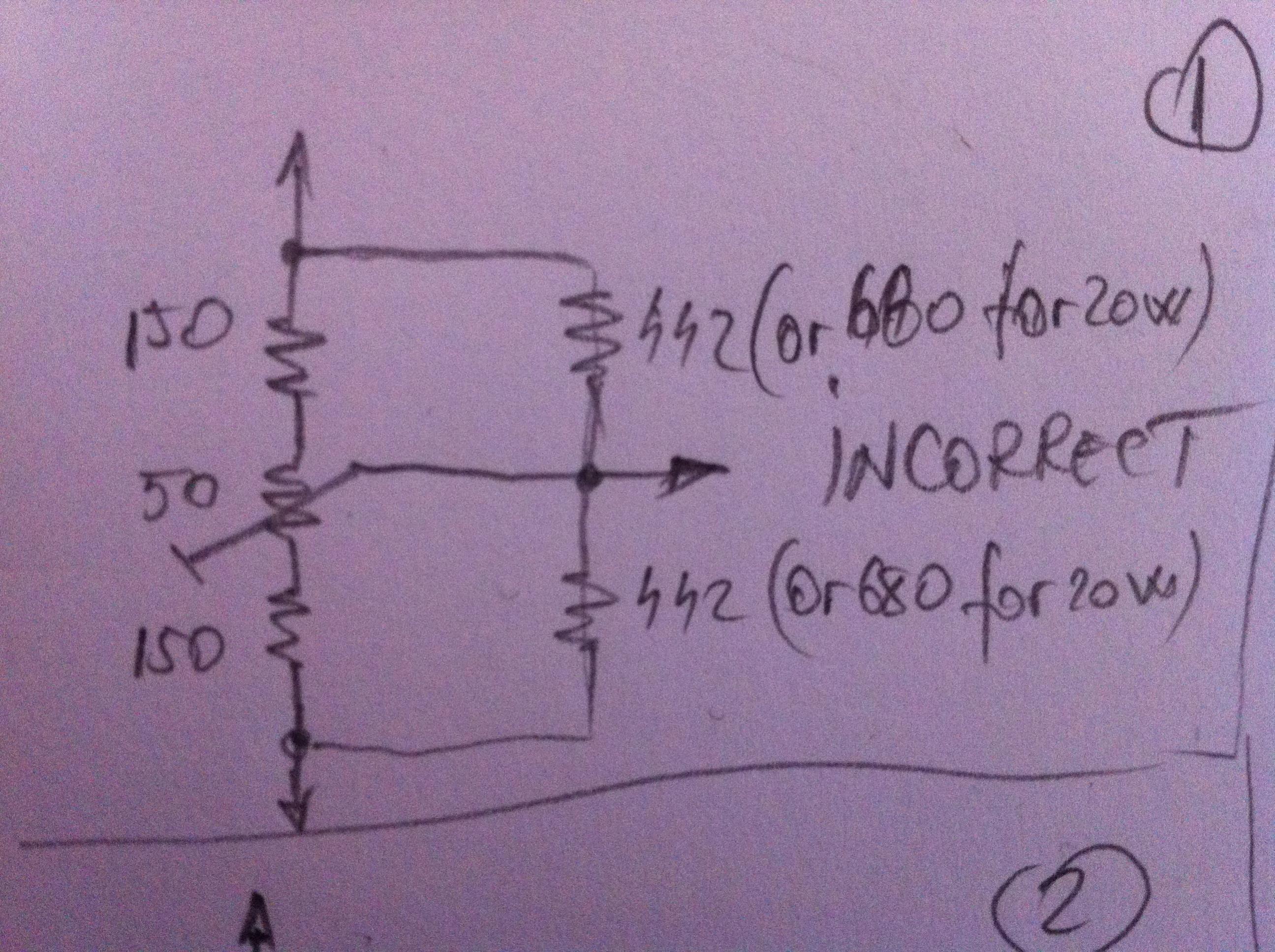
The 10R are not in parallel with the 442R, correct? Or another way, the 10R are in series only with the track of the potentiometer?
If so, good. Change 442R to something bigger... Add 100R or similar in series, make 542R.
Yes the 10 ohm resistors are in series with the trimpot like in the image below.
http://www.diyaudio.com/forums/atta...601d1422696301-hiraga-20w-class-img_2998.jpg?
Last edited:
Hi Zen Mod,put 1K trimpot in series with 1K8 and fiddle
Done that from the begining but nor much happend, it lowered the bias from 0,78v to 0,74v.

This amp is like the bermuda triangle now i could tell this for shure..
Thanks
Change 442R to something bigger... Add 100R or similar in series, make 542R.
I will do that tomorrow. Thank you very much.
I will do that tomorrow. Thank you very much.
I told you the same for the offset.
Also you can try to reduce the Zener Diode by 2V lowering the bias..
Increasing the 1.5K to 2K that supposed to reduce also the bias
Sergiu,
This amp is notoriously for using the correct transistors.
If you have the offset below 100mV, and you are using a complete set of active devices, you are doing well.
You wll notice that T1 and T2 are supplied at regulated voltage, and if the voltages at emitter are 662mV and -776mV it looks pretty good, BUT, you have measure around 0.5-1mA across the 1k5 resistors on collectors of second pair of devices. I think you have around 0.181V and 0.175V on these 1,5k resistors so clearly you are NOT turning on the drivers and outputs.
You should decrease the two 43k resistors on the emitter to rail on BOTH sides; leave the 180R and 240R resistors on the emitter of T1 and T2 the same. This value is pivotal and changing th drive through the emitters of the second stage devices.
You are essentially redesigning the amp again to suit modern transistors and this involves a lot of measuring and fiddling.
I think your amp is OK, it just has an offset issue?
Hugh
Last edited:
Sergiu,
This amp is notoriously for using the correct transistors.
If you have the offset below 100mV, and you are using a complete set of active devices, you are doing well.
You wll notice that T1 and T2 are supplied at regulated voltage, and if the voltages at emitter are 662mV and -776mV it looks pretty good, BUT, you have measure around 0.5-1mA across the 1k5 resistors on collectors of second pair of devices. I think you have around 0.181V and 0.175V on these 1,5k resistors so clearly you are NOT turning on the drivers and outputs.
You should decrease the two 43k resistors on the emitter to rail on BOTH sides; leave the 180R and 240R resistors on the emitter of T1 and T2 the same. This value is pivotal and changing th drive through the emitters of the second stage devices.
You are essentially redesigning the amp again to suit modern transistors and this involves a lot of measuring and fiddling.
I think your amp is OK, it just has an offset issue?
Hugh
Hi Hugh,
Thank you very much for the info. I have to say that i dont have an offset problem, i was playing with the 180/240ohm to increase the voltage across the 1k5 and to make equal biass across both of them, wich i did with succes. My problem is that i couldnt lower the bias bellow 2.3amps..
Something is not permitting me to go bellow that value even if the rest of the amp is in parameters as described in the schematic..
Sergiu,
The quiescent current is set by the voltage at the base to rail of the two drivers.
This is set by the current through the second stage complements; so this depends on the Vbe of the two input transistors, the two 43k resistors, and the resistor string between the emitters of the second stage. ALL are interdendent, which of course mandates the transistor choices.
I haven't the time to go through the 75 pages here, but I believe people have told you you need to play with the interemitter resistor string; it should be INCREASED to reduce the current across the two 43k resistor, which in turn sets the base to rail of the drivers and therefore the voltage dropped/quiescent current through the 0.33R resistors. This is a high fb amp, so you could also reduce the two 43k resistors down to 33k each. If this is not satisfactory, increase the 2 x 442R on the centre string to say 2 x 680R, and try again........
If you have the offset OK, the next step should not be too tricky........
Hugh
Thank you very much for the help Hugh.
The offset is now 0.022v and rock stable. Today or tomorrow i have to adjust and test these amps and finish them.
I'm really upset because i'll start my job again in twoo weeks and will not have this much time as now. I have to adjust the amps fast.
Thank you very much for the help my friends. I'll post again the results in this evening.
I told you the same for the offset.
Also you can try to reduce the Zener Diode by 2V lowering the bias..
Increasing the 1.5K to 2K that supposed to reduce also the bias
Sorry for my misunderstanding. How do i reduce the zener diode, by increasing the 1k1 resistor?
If i increase the 1k5 to 2k the bias goes higher and i have the same result by decreasing the 33k resistor.
Yes, Sergiu, it will reduce the quiescent current, but it will reduce the rail efficiency (not such peak voltage at the load) and it will increase the Zout a little, which is not good for this design.
Cheers,
Hugh
You are right. I was just thinking..
I seen allot of colleagues that did this amp with mje15034/35 or BD237/238 with a beta of around 40-60 and it works and adjust easyly. All of the transistors that i have for the diver stage have a minimum beta of around 110-150.. I think that this is the real motive that the bias is so hight..
The driver stage has across the B-C exactly 0,6v (exactly as in the schematic), so this means that the driver stage is opened and works perfectly now but gives allot of current to the output. How can i limit that?
Hught i can tell you that i tried all the "tricks" on the input to lower the bias but doesnt work, even with the input, buffer and driver subtensioned (transistors received half the curtent and the voltage) the bias doesnt go lower than 0,67v.
With all the voltages and all the biases corectly adjusted across the input and driver stage (and being equally on both sides) this is the lowest bias that i can get of aprox 0,74v (with all the stages working optimally)..
Should i put two 100ohm trimpots directly on the base of the final transistors and slowly adjust to go lower with the bias plus increasing the 1k8 value to decrease the bias?
Also i want to do what 6L6 told me to increase the 442 to 542ohm resistors. What do you say about this combined with what i told you in the above statement? Or should i try this first (increase to 542 the 442 resistor)?
Thanks
Sergiu
Last edited:
Sergiu,
After studying this circuit I can see that the significant influence on the quiescent current control is the two 442R resistors.
If you increase this to 560, or even 680, you will reduce the current through the second stage, and this will then reduce the current through the second stage, and specifically, through the two 1.5K collector resistors which drive the drivers.
So, if you increase these 442R resistors to around 510R I believe this will reduce the quiescent at the output stage from 2.3A down to around 1.5A.
Good luck, and let us know what happens!
Cheers,
Hugh
Give us some good news Sergiu,
Are you listening to nice music yet ?
Hi Daniel,
Sorry for the delay. I was out of town yesterday and posted from my phone.
Not listening yet, the bias is still hight...
)))Sergiu,
After studying this circuit I can see that the significant influence on the quiescent current control is the two 442R resistors.
If you increase this to 560, or even 680, you will reduce the current through the second stage, and this will then reduce the current through the second stage, and specifically, through the two 1.5K collector resistors which drive the drivers.
So, if you increase these 442R resistors to around 510R I believe this will reduce the quiescent at the output stage from 2.3A down to around 1.5A.
Good luck, and let us know what happens!
Cheers,
Hugh
Hi Hugh,
Thanks for the hints.
I did the following today:
Rised up the 180 ohm to 200ohm and 240 to 260ohm trimered values, this equilibrated the voltage across the bases of the drivers perfectly.
Next, i increased the 442 ohm with two 110 ohm resistors wich gave 552 ohm per total, this has lowered the voltage across the 1k5 resistors and gave me 0.6mA across them. I lowered the 1k5 resistors to 400 ohm now wich gave me a bias across the "1k5" of 0.9mA and a slight decrease of bias to just 0.734V..
))) The 0.6V acros B-C of the drivers is now 0.611V (and can be lowered abit but doesnt affect too much the bias).
I adjusted the offset to jus 2mV now.
So everything is now perfect except the bias..
)I changed the Toshibas 2sa/2sc drivers from the previous posts to the other channel wich has Fairchild A grade 2sa1220a/2sc2690A with Y suffix for the beta and unfortunetly i have the same quiescent current results.
Last edited:
- Status
- This old topic is closed. If you want to reopen this topic, contact a moderator using the "Report Post" button.
- Home
- Amplifiers
- Solid State
- Hiraga 20W class A