Does my measurements means that i have a blown buffer?
I'll go and measure them now.
I measured the input and buffer and they seem to be ok.
I forgot about the beta that i used. The beta on the input on both channels is between 612 and 618 for all the 4 transistors on each channel..
Is this too high?
Last edited:
Hi Sergiu
My advise to you to go back to the original circuit with out modifying or replacing any resistor values.")
Pick one of the circuit witch V is closer to your power supply under load
or calculate
for example 18VAC X 1.2 to get DC in class A.
I built both of these (I used the original transistors) and replacement to no issue at all.
It was rock stable and very little offset movement (a few mV) difference between warm up or cold amp.
Again please do not replace any resister or ad anything for fine tuning. No need for
You just run into trouble!
In case if you need layout I can look up somewhere my old layout, you can month the power transistors into the PC boards in case if you are using TO247 package (not TO3)
Please take a look at the original 20W & 30W circuit!
My advise to you to go back to the original circuit with out modifying or replacing any resistor values.
Pick one of the circuit witch V is closer to your power supply under load
or calculate
for example 18VAC X 1.2 to get DC in class A.
I built both of these (I used the original transistors) and replacement to no issue at all.
It was rock stable and very little offset movement (a few mV) difference between warm up or cold amp.
Again please do not replace any resister or ad anything for fine tuning. No need for
You just run into trouble!
In case if you need layout I can look up somewhere my old layout, you can month the power transistors into the PC boards in case if you are using TO247 package (not TO3)
Please take a look at the original 20W & 30W circuit!
Attachments

I would set up the proven original circuit either of them.
After if you want to replace some parts for fine tuning or for any other reason do it step by step. (But no need for that to me worked always from the first fire up).
If you run in trouble you would have some idea what happened, you can always go back to the previous state or try to resolve the issue.
Greetings
I would set up the proven original circuit either of them.
After if you want to replace some parts for fine tuning or for any other reason do it step by step. (But no need for that to me worked always from the first fire up).
If you run in trouble you would have some idea what happened, you can always go back to the previous state or try to resolve the issue.
Greetings
Hi Gaborbela,
You are right. After rereading the three articles from l'audiophille i found something very interesting:
a) the hfe on the input has to be 400-500 or max 550 (the E grade for the originall trannies), and in my case it should be bc550/560B and mynes are C grade with approx 615 Beta wich is really high;
b) i had to have 0.6v on the buffer base with ground refference for measuring, and because of the high beta of the input now i have +0.73v and -0.78v (with 180ohm in the "1k5" place) wich takes the byas really high;
I cannot change the input trannies because i have to wait for 3-5 days to get another originall batch of B grade from Farnell and then rematch them. I got allot of them with close beta around 580 but they are still not enought low beta.
I think that i have to modify the 180/240 ohm resistors to lower the input of the buffer.
In conclusion I think that this amp should have beta around 400-500 for easy biass offset.
Thank you very much for the ideas.
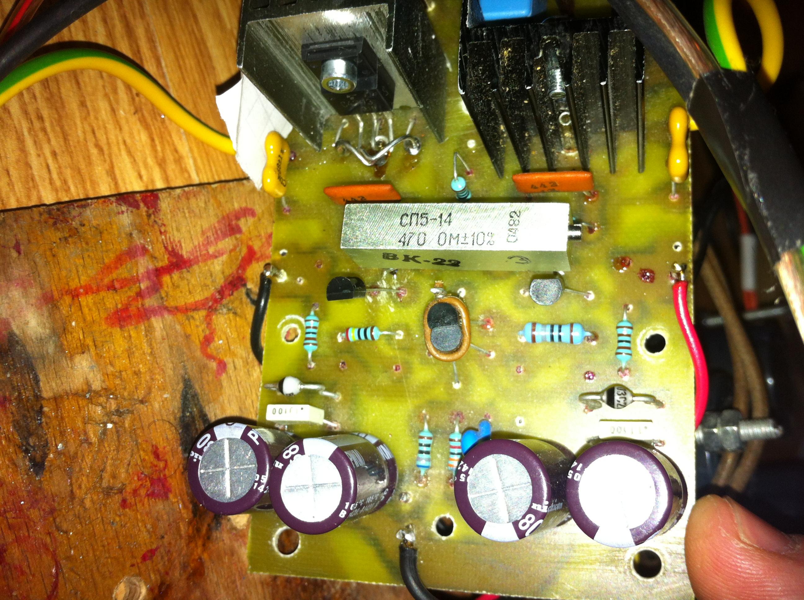
That was the first pot that i used from the second l'audiophille sugestion notes but this is incorrect (the bellow picture).
Now i have a 470 ohm trimmer (because at my local store i didnt find 500 ohm Bourns or multiturn Bourns) in series with two 10 ohm resistors.
I'm using a russian type 470one wich gives in series with the two 10R resistor and parralled 442R an approx of 157.8 ohm for each half of the trimmer. With the original 500 ohm you will have approx 159.8 wich i think that is not so much difference. With this arrangement i have an offset of 5mV.
I tested and found the same good results (like 470+(2*10)) with 2*220 ohm resistors with 100ohm multiturn trimpot altought with this arrangement we have approx 167 ohm per half trimmer i managed to adjust the offset to 8mV .
Please excuse my rought english.
Cheers
Last edited:
That was the first pot that i used from the second l'audiophille sugestion notes but this is incorrect (the bellow picture).
Now i have a 470 ohm trimmer (because at my local store i didnt find 500 ohm Bourns or multiturn Bourns) in series with two 10 ohm resistors.
I'm using a russian type 470one wich gives in series with the two 10R resistor and parralled 442R an approx of 157.8 ohm for each half of the trimmer. With the original 500 ohm you will have approx 159.8 wich i think that is not so much difference. With this arrangement i have an offset of 5mV.
I tested and found the same good results (like 470+(2*10)) with 2*220 ohm resistors with 100ohm multiturn trimpot altought with this arrangement we have approx 167 ohm per half trimmer i managed to adjust the offset to 8mV .
Please excuse my rought english.
Cheers
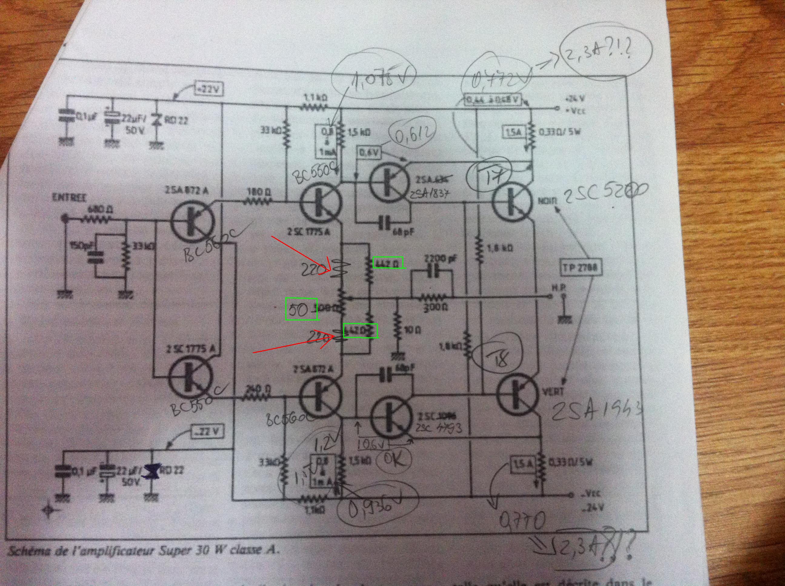
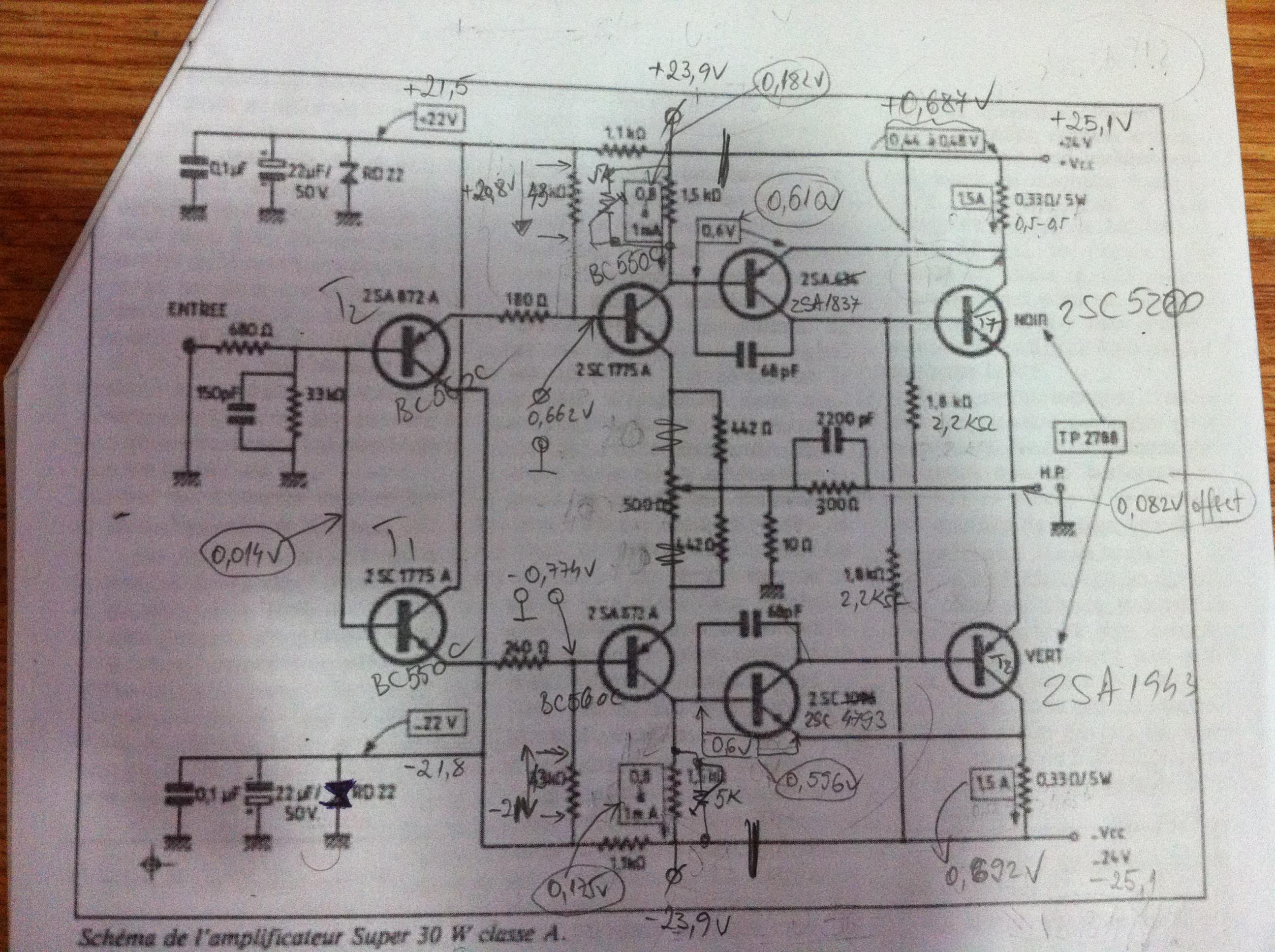
In the bellow picture we have the actuall arrangement that i'm using now:
And actual measurements:
Last edited:
I think the C grade BC550 & BC560 is great!
Do not change that. B grade has way to low hfE and much worst quality compare to ON semi C grade..
Around the trimmer use only those resistors which is at the original circuit.
Try to replace the 442R with 500R both side, se if you can get better offset or worst.
470R trimmer is OK I did use that to.
Total bias for one channel please let me know
If your bias to high please lower the Zener diode by two Volt or so..
Why do you have 4PC electrolytic on each board
Your offset not to bad you can test the amplifier if you do not have other problem.
Now i'm abit frustrated. I played with the 180/240R resistors and now i have balanced perfectly the amp. I have 1.1mA and can readjust this value lower for each rail.. 0.6v on each driver. I let the offset at 0.016V. Just perfect..
There is a BUT, and that is the stupid bias at 0,756v with a value of aprox 530 ohm for the 1k5.. And now i'm really mad...
There is a BUT, and that is the stupid bias at 0,756v with a value of aprox 530 ohm for the 1k5.. And now i'm really mad...
I have a total of 4x 680uF/35v, two per each rail for lower impedance, lower esr and some more juice on the low frecv..
If you have good power supply I don't think you need those big caps on the PC board.
I tested some audio capacitors there Silmic & Nichicon Gold
To me 100nF paper Rifa did the trick, sounded the best - no electrolytic caps.
Make sure keep the wire as short as possible from the PS cap bank to the PC boards. And use at least 14AWG wire about 1.5mm min. Ground can be even thicker 2mm or so.
I used capacitance multiplier from the R Elliot site for best result.
Only problem with that you need very good quality transistors there, even do it works most of BJT you pick but sound wise it make a big difference..
At first make these work and after you can try some upgrade.
Greetings
Now i'm abit frustrated. I played with the 180/240R resistors and now i have balanced perfectly the amp. I have 1.1mA and can readjust this value lower for each rail.. 0.6v on each driver. I let the offset at 0.016V. Just perfect..
There is a BUT, and that is the stupid bias at 0,756v with a value of aprox 530 ohm for the 1k5.. And now i'm really mad...
You want to increase the V on the 1.5K increase the value of that resistor both side 1.8K or 2K
Last edited:
If you have good power supply I don't think you need those big caps on the PC board.
I tested some audio capacitors there Silmic & Nichicon Gold
To me 100nF paper Rifa did the trick, sounded the best - no electrolytic caps.
Make sure keep the wire as short as possible from the PS cap bank to the PC boards. And use at least 14AWG wire about 1.5mm min. Ground can be even thicker 2mm or so.
I used capacitance multiplier from the R Elliot site for best result.
Only problem with that you need very good quality transistors there, even do it works most of BJT you pick but sound wise it make a big difference..
At first make these work and after you can try some upgrade.
Greetings
I have all the wires, except the ones that goes from the input psu of 2.5 mm diam.
Thank you very much for the sugestions.
He want's to decrease bias - so the 1.5K need to be bigger, 1.8 or 2.2K
Sergiu - Do you have the 5K pots in parallel with 1.5K? Or is the 1.5K removed? If parallel, increase resistor to at least 2.2K and try again to adjust pot for desired bias.
Hi Jim,
Yes i really need to lower the stupid bias but cannot do that and dont know why..
Because it was hard to unsolder the trimpot and 1k5 every time to measure the value and because i cannot measure directly on the pcb those two (the impedance raised every time like i had a capacitor in parallel), i unsoldered those two and replaced with 1k trimpot. And if i lower this trimpot's value the bias goes down so i lowered from 1k5 to 520 ohm and i have 0.518v across it (1mA) so its perfect and 0.6v across the B-C of the drivers (perfect here too) but i cannot lower the bias furten than the value specified in the above post.
If i decrease the 1k5 further the voltage across it decreases too, and then i increase the 180/240 ohm and decrease the 33k to compensate this effect and have an approx result : the bias is now 0.71 and after readjust the offset the bias goes to 0.725v again.
I really dont understant whats happening here and switched from left channel with 2sa1837/2sc4793 to the right channel witch has the 2sa1120a/2sc2690a pair of drivers and have the same result...
Please help!
Sergiu - what resistors do you have from the offset pot to the transistors? 442R and parallel 200R? Only 200R? And what is pot value?
Now i have a 470 ohm multiturn trimpot in series with two matched 10 ohm MF 1% 0.6w resistors and paralelld with two 442r 1% 0.5w metal film matched resistors wich gives approx the same value of 160ohm per half trimmer as the single 500ohm trimmer plus 2x442r resistors..
You want to increase the V on the 1.5K increase the value of that resistor both side 1.8K or 2K
I seen that if i increase the 1k5 i increase the bias. The same result is obtained when i decrease the 33k or the 1k8 from the input's base transistor.
If we lower the 180/240 ohm we lower the buffer base voltage and the buffer Ic but if we increase the we get a higher bias across the 1k5..
With the value of the 1k5 lowered to 190ohm i have a bias of 0,65v, and if i lower the 1k5 even further to say a value of 150 i got 0,84v bias.
Last edited:
- Status
- This old topic is closed. If you want to reopen this topic, contact a moderator using the "Report Post" button.
- Home
- Amplifiers
- Solid State
- Hiraga 20W class A