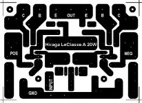
Use these layout , you can open with paint program .
Magnified 6x and fix a bit . After save it and U can use it .
Is better design than the orig .
There is 4 jumper .
I will mark in the next post . Use solid wire for the jumper to .
The colored lines are jumpers , one more time use solid wires .
I hope these help.
Greetings
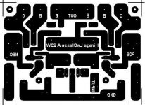
Magnified 6x and fix a bit . After save it and U can use it .
Is better design than the orig .
There is 4 jumper .
I will mark in the next post . Use solid wire for the jumper to .
The colored lines are jumpers , one more time use solid wires .
I hope these help.
Greetings
Attachments
guys,
gaborbela is absolutely right, the TOSHIBA stamped transistors are actually counterfeit from china, they got fried easily. ; i will be waiting for Olafs comments after he builds his Hiraga. Meanwhile i'll be looking for Susan Boyles winning song to be played on my class A ss amp. I prefer it on audio cd of course, not on mp3's.
regards to all
efren
gaborbela is absolutely right, the TOSHIBA stamped transistors are actually counterfeit from china, they got fried easily.
; i will be waiting for Olafs comments after he builds his Hiraga. Meanwhile i'll be looking for Susan Boyles winning song to be played on my class A ss amp. I prefer it on audio cd of course, not on mp3's.regards to all
efren
Hello Erik
I took from a Russian website .
Sorry I did't knew that .
http://mohm.ru/index.php/artcls/42-amps/58-hiraga
Regards
I took from a Russian website .
Sorry I did't knew that .
http://mohm.ru/index.php/artcls/42-amps/58-hiraga
Regards
gaborbela said:Hello Erik
I took from a Russian website .
Sorry I did't knew that .
http://mohm.ru/index.php/artcls/42-amps/58-hiraga
Regards
No problem, I was just curious..... The original is here:
http://memweb.newsguy.com/~stigerik/html/body_hiraga_leclasse_a_20w.html
taotao said:Oh, I forgot:
Dan, where did you buy this big electrolytics?
Max. I find is 0.02F.
Thanx
Olaf
Hi olaf,
I bought the large electrolytics off ebay.
If you want some original parts i have all the original inputs and toshiba 2SC5200/2SA1943. but better email me direct:
(dont want to upset anyone)
danw1million@hotmail.com
or look here;
http://www.diyaudio.com/forums/showthread.php?s=&threadid=142643
-Dan
Hi Guys!
I just finished the 2nd design of my Hiraga Class A.
The 1.0 version used BC556B/546B BD139/140 and 2SA1943/SC5200. The 2nd one uses BC557B/547B MJE253G/243G and same Toshiba output.
All of the other components value are same, but the first version had 1,1A current, the 2nd one has only 0,7A.
This difference could be caused by different beta values? (556B~320 557B~330 BD140~180 MJE253G~140) Or what?
I'm seeking for some other types of transistors with higher beta, but I bearly found calculable source.
My Hiraga v1.0, 2.0
Chiao!
Hi Guys!
ther components value are same, but the first version had 1,1A current, the 2nd one has only 0,7A.
This difference could be caused by different beta values? (556B~320 557B~330 BD140~180 MJE253G~140) Or what?
I'm seeking for some other types of transistors with higher beta, but I bearly found calculable source.Chiao!
Try KSC2690A/KSA1220A as driver. I have some of them and the hfe is about 250, but some of them goes up to 300
Regards:Sajti
Are you puting resistor in series to the large capacitrs to reduce inrush current or use NTC resistor in series with primary winding?
in power amp PSU (strictly in A class) resistors are used as bleeders or part of CRC filter ;
using them as first element ( in RC configuration ) is no-no .
so - you can't expect to use them on secondary side for inrush current limiting .
that biz is always made on primary side , just because in same time you are limiting inrush current of entire system , not just smoothing caps
Last edited:
what resistors are they that you used ?
I used Beyschlag resistors.
There are benefits and drawbacks, too.
Benefits: can handle 1W power, accurate values - 1%, E24 resources, and one more thing, wich is important at this building method: it has strong, gross outlet. It usefull to make the circuit massive at this case.
The main drawback is the magnetic outlet and body. I'll change the most important resistors, if I have no more ideas to make the amp better.
Chiao.
- Status
- This old topic is closed. If you want to reopen this topic, contact a moderator using the "Report Post" button.
- Home
- Amplifiers
- Solid State
- Hiraga 20W class A