Hi Gaborbela,
I have not biased it higher because i have not purchased any more resistors yet. plus i will need to put some larger heat sink and also got to something like 200-250W rating power transistors.
I will probably re-bias it to 1.5A which will be ample (~50W class A)
however this will be running HOT
I have not biased it higher because i have not purchased any more resistors yet. plus i will need to put some larger heat sink and also got to something like 200-250W rating power transistors.
I will probably re-bias it to 1.5A which will be ample (~50W class A)
however this will be running HOT
Hello Daniel
Yes I know that , lot of heat !!!Winter is coming in Canada . But Hiraga only bring the sound quality higher level under heavy bias .
I built one Hiraga 10 years a go with low bias 0.9A 20W verision but the sound was not my taste , not even close .
After I did some research and I found out the min. at least 1.5A bias that bring the sound higher level .Of course with changing the Sender diode that not just bring the bias higher but the front get more voltage. The 13V Sender diode at the Hiraga site very bad idea .My first amp I built after that schematic , terrible sound com pair what Hiraga can provide with the 22V Sender diode.
So even now I will go with a higher power supp voltage I want to keep min1.5A bias .
If my heat sink can take the heat even I will try to go higher may be 2A .
These amplifier need lot of attention , and patient to bring out the best of it .
You can imagine 10 years a go built my firs Hiraga and I still not give up on it .
Try to buy some Russian Teflon or PIO capacitors , use them on the PC board .. They will do miracle believe me .
Those amplifiers with the minimal parts very selective to the parts are used .
Greetings
Hi all,
Finally some more work on the Hiraga amp......
After using and listening to it...
I have to admit wavebourn is right about the heatsinks/ orientation i was using, they are now going to be upright and larger.
The speaker protector i was using does not support large enough cable so i have a newer one with muting etc..
the PCBs and speaker protector will be mounted on top of the chassis per the original style which is easier to adjust when running.
Bias is too low at 0.7-0.8A i plan to increase to 2 amps or greater.
-Dan
Hiraga Le Class A the journey continues....
In the holiday break, I did some work on the Hiraga Le class A amp...
I was trying to get it finished to take to my friends house in melbourne.
Spent from 7am until about 3pm on 26-12-08 working on the Hiraga amp..... (yes 8 hours straight...)
Every thing was going well until lunch time.
Here is the list...
Snapped an M3 screw in the heatsink.....
Re drilled the hole through the screw.
snapped an M3 tap in the new hole.
drilled another hole. snapped a second M3 tap. (fairly angry by now.....)
moved the transistor another 20mm over.... used a self tapper (not happy!!!!!)
worked on it until about 2.30 put it all back tog....
powered it up it was working well. decided to adjust the bias to the normal level....
Then dropped a multimeter probe and just my luck it shorted between the driver stage transistor leg. off clicked the DC protect.... sadly could not bring the hiraga now it needs alot of work.... new channel transistors resistors etc
Had a quick go at replacing a resistor and the driver stage..... no luck........
ran out of time unfortunately so the amp stayed home.
the saga continues.
See the pics attached
-Dan
In the holiday break, I did some work on the Hiraga Le class A amp...
I was trying to get it finished to take to my friends house in melbourne.
Spent from 7am until about 3pm on 26-12-08 working on the Hiraga amp..... (yes 8 hours straight...)
Every thing was going well until lunch time.
Here is the list...
Snapped an M3 screw in the heatsink.....
Re drilled the hole through the screw.
snapped an M3 tap in the new hole.
drilled another hole. snapped a second M3 tap. (fairly angry by now.....)
moved the transistor another 20mm over.... used a self tapper (not happy!!!!!)
worked on it until about 2.30 put it all back tog....
powered it up it was working well. decided to adjust the bias to the normal level....
Then dropped a multimeter probe and just my luck it shorted between the driver stage transistor leg. off clicked the DC protect....
sadly could not bring the hiraga now it needs alot of work.... new channel transistors resistors etc Had a quick go at replacing a resistor and the driver stage..... no luck........
ran out of time unfortunately so the amp stayed home.
the saga continues.
See the pics attached
-Dan
Attachments
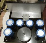
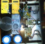
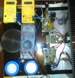
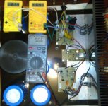
Did some more work on the amp today....
replacing all the transistors in the sick channel.
worked in the bias to see what level i can run
1.5A gave me about 50 degrees C (absolute)
1.75A gave me about 59 degrees C (absolute)
2A gave me about 62 degrees C (absolute)
All at an ambient temp of 31 degrees C...
See attached pic of horrible biasing setup(s) !
(mV/0.33 Ohm on the yellow meters, temp on the grey meter.)
-Dan
Attachments
Good Question Nrik,
It was a trade off between keeping the input and output leads as short as possible and centered or having approx 8 cm of leads to the output stage.
i did not measure any problem at this length, when i have the amp completed and re-biased with fixed resistors (hopefully in a couple of days i will put it on the cro and see the results. i dont expect any problems with lead inductance or capacitance at this length though.
-Dan
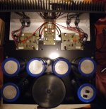
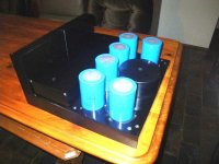
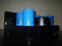
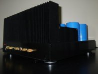
FINALLY WORKING!!!!!!!!
Hi all,
Replaced the popped transistors in the Le class A tonight and tidied up some wiring...
re- biased the amp and it is running....
i am running 1.5-1.6A bias and it runs at about 60 deg C once it is stable...........
IMO the sound is very good.
a few more pics attached.
Hi all,
Replaced the popped transistors in the Le class A tonight and tidied up some wiring...
re- biased the amp and it is running....
i am running 1.5-1.6A bias and it runs at about 60 deg C once it is stable...........
IMO the sound is very good.
a few more pics attached.
Attachments
Hiraga 20 Watt class A
Nice thread gentlemen!
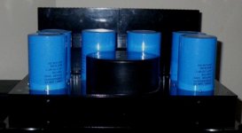
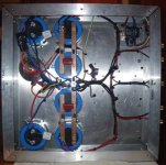
Just hauled an amp down from the attic last night that a friend of mine gave me - it sounded "ok" he said - but the reason I got it was to use the 8 fine Rifa 47000uF Electrolyts for other DIY projects. Then, while is was up on the attic, I took a look at it, and realised from the circuit layout that it looked like the Hiraga 20 Watt Class A amp. So down in the living room with it, dusted it off - plugged it in the mains and monitored dc offsett for about half an hour - then plugged in the speakers - result: nice smoth, airy soung - bass is there, but not very firm. Very good at resolution in the sense that it is easy to hear low level sounds between more powerfull sounds - i.e. other "background" instruments in an orchestra that easy gets "smeared". However, perspective seems limited compared the to 3886 chipamp I normally use.
Compaired with the pictures of circuits in this thread - it indeed IS the Hiraga Class A.
Trannie is crap (small, humming), heatsinks are small (uses a noisy fan) and there is an ugly protection circuit placed between output devices and speaker terminals. But the worst thing is looks like the constructor has compensated for the smallish heatsinks by running it at 0,5 A bias (0,22volt over 0.44R resistors) - and this is using +/- 28 volt of DC supply!
Actually I like the sound so muct that this amp should get a proper chassis (build on a wooden plate right now) and some proper heatsinks - that together with a larger Trannie should allow for some appropriate BIAS - hope that this will help on the soundstage issue...
But nice thread - lots of nice info and pictures!
Kind regards
Hans
Nice thread gentlemen!
Just hauled an amp down from the attic last night that a friend of mine gave me - it sounded "ok" he said - but the reason I got it was to use the 8 fine Rifa 47000uF Electrolyts for other DIY projects. Then, while is was up on the attic, I took a look at it, and realised from the circuit layout that it looked like the Hiraga 20 Watt Class A amp. So down in the living room with it, dusted it off - plugged it in the mains and monitored dc offsett for about half an hour - then plugged in the speakers - result: nice smoth, airy soung - bass is there, but not very firm. Very good at resolution in the sense that it is easy to hear low level sounds between more powerfull sounds - i.e. other "background" instruments in an orchestra that easy gets "smeared". However, perspective seems limited compared the to 3886 chipamp I normally use.
Compaired with the pictures of circuits in this thread - it indeed IS the Hiraga Class A.
Trannie is crap (small, humming), heatsinks are small (uses a noisy fan) and there is an ugly protection circuit placed between output devices and speaker terminals. But the worst thing is looks like the constructor has compensated for the smallish heatsinks by running it at 0,5 A bias (0,22volt over 0.44R resistors) - and this is using +/- 28 volt of DC supply!
Actually I like the sound so muct that this amp should get a proper chassis (build on a wooden plate right now) and some proper heatsinks - that together with a larger Trannie should allow for some appropriate BIAS - hope that this will help on the soundstage issue...
But nice thread - lots of nice info and pictures!
Kind regards
Hans
- Status
- This old topic is closed. If you want to reopen this topic, contact a moderator using the "Report Post" button.
- Home
- Amplifiers
- Solid State
- Hiraga 20W class A