I have no plan for driver maintenance. As far as I can tell I am going to have to install the woofers as I make the box.
I suggest you seriously reconsider this design then. All it would take would be one bad cable or faulty connection to one of these woofers make your life miserable.
Off the top of my head, there are at least to other configurations that might work, e.g. (1) a slot-loaded 4th order BP system, where the slot extends from the top down the side and to the bottom where the front chamber holding the drivers is loaded. Leaving the bottom panel removable will then provide the needed access to the drivers. Also, here's a 6th order BP system idea - use a vertical panel to divide the box into two separate chambers that both vent to the outside via the side of the box that faces that hole. In this case leaving one of the side panels removable will give you the access you need to the drivers. In both cases you'll need to take the box out to access the drivers. I'm assuming that's not going to be an issue.
Interesting. I like your 6th order idea. I am going to spend some time mocking that up with the space I have. Stay tuned.
Yea removing the box is not going to be an issue.
Yeah, you will need to access to the drivers at some point. There's a million things that could go wrong, even the screws could come loose - not probably but possible. Drivers can blow, wires come loose, and despite your best efforts there will probably be water damage at some point. Technically you can access them anytime by cutting a hole in the box if you need to but adding an access panel or keeping the top or bottom removable will be easier in the long run.
To find out which side is causing the resonances, just remove the slot load part from the sim completely and see what changes. Just sim it as a simple ported box. OR add stuffing to one section or the other (if Hornresp will allow it, I haven't played with a design like this yet with stuffing).
But first, you are simulating with resonances NOT masked, right? You want to see all the resonances before you start working on eliminating them.
BTW, taking a quick look back it looks like I posted a design in post 35 that didn't have much problems with resonances. Were you not able to achieve something like that?
Can't remember if I masked resonances or not with that sim, but might have if I didn't know your desired dimensions at that point. Easy enough to check if you want to.
You should be able to come up with something with a pretty smooth response with the high and low pass filters in place. Something that doesn't require much if any stuffing for the higher resonances.
BTW, taking a quick look back it looks like I posted a design in post 35 that didn't have much problems with resonances. Were you not able to achieve something like that?
Can't remember if I masked resonances or not with that sim, but might have if I didn't know your desired dimensions at that point. Easy enough to check if you want to.
You should be able to come up with something with a pretty smooth response with the high and low pass filters in place. Something that doesn't require much if any stuffing for the higher resonances.
Yes is am simulating with rear chamber resonances turned on.
Back in post 45 you had said you masked chamber resonances. Once I put a real value in for Lrc and unmask resonances it does get a bit worse. Also I had a hard time with the long port length. Your sim used more power than I had available too, so when you compare it to my most recent sim it has less SPL however it does play much lower.
To find out which side is causing the resonances, just remove the slot load part from the sim completely and see what changes. Just sim it as a simple ported box. OR add stuffing to one section or the other (if Hornresp will allow it, I haven't played with a design like this yet with stuffing).
But first, you are simulating with resonances NOT masked, right? You want to see all the resonances before you start working on eliminating them.
Yeah I have been simulating with resonances on. From playing around a bit it looks like the resonances are coming from the rear chamber.
There should be at least some resonances coming from the front chamber. If there's only a 2 inch gap there's no room for stuffing in there though.
Stuffing the rear chamber will calm the rear chamber resonances down. Keep any stuffing well away from the port. Light stuffing or lining will be helpful but it won't completely remove the spikes unless you use heavy stuffing.
That's really your only option short of redesign.
Have you reconsidered an access panel or removable panel? Or are you just going to cut into the box when/if needed?
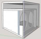
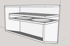
I might consider an access panel, but for fun I tried the 6th order idea and this is what I got. I had a hard time getting enough port area and thus port velocity is high.
I simulated it as a 6th order bandpass (I think I did it right) with a .75 inch long port (thickness of plywood) for the front chamber.
I like the smoother high freq response of this option but I am wondering if the differences come down to modeling it as 6th order as opposed to a offset horn.
I simulated it as a 6th order bandpass (I think I did it right) with a .75 inch long port (thickness of plywood) for the front chamber.
I like the smoother high freq response of this option but I am wondering if the differences come down to modeling it as 6th order as opposed to a offset horn.
Attachments
The thing about a tapped horn is that it is really much like an undamped resonant pipe at the top end of the response which causes those horrible peaks and dips. If you want to have a wide and usable top end then it is not the way to go.
Your bandpass design looks a lot better but I'm not sure that I trust that simulation, based on what I've seen of Hornresponse it is very optimistic on box size. You could try the bandpass simulation in another tool to confirm the box size.
Passive radiators are one way to get rid of the distributed pipe resonances but you'd need a pair with very long throw, CSS 15" perhaps.
Last edited:
(I think I did it right)
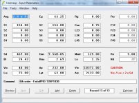
No you didn't do it right.
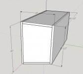
10371 cu cm (Vtc) divided by 2133 sq cm (Atc) = 4.86 cm chamber length. That MIGHT be the actual width of the chamber (from driver baffle to outside wall) but you want the chamber LENGTH, not the chamber WIDTH. The length mode resonance is what you want to see, not the width mode resonance. The length of the front chamber is at least 60 cm, considering the fact that there's two 12s side by side. Same as the last design.
And this should also be simulated as offset driver too so you can capture the actual offset nature of the driver location along the chamber length, just like the last design.
Also, I can't see in the pic how the vent attaches to the rear chamber. Depending on where it is, there's probably a sizable change in cross sectional area, and that should be included in the sim, although Hornresp won't be able to do it if there is a big csa change.
And just to be sure, what did you base your Vrc on? Is it actually 73 cm long or is that number just a placeholder for now?
I like the smoother high freq response of this option but I am wondering if the differences come down to modeling it as 6th order as opposed to a offset horn.
The differences come down to the unreasonably small length of the front chamber. It's 60+ cm long, not 4.86 cm long. Also, make sure Vrc is correct, port length is correct and you sim with resonances unmasked.
FWIW, this is almost exactly the same as your last design. Ported slot loaded = 6th order bandpass. The ONLY significant difference between this one and the last one is that it's laid out differently and you blocked part of the front chamber terminus on this one. Otherwise it's pretty much the same thing, it even visually looks like the same thing with very minor dimension changes and layout, I'm surprised that you simulated it differently (and really wrong).
Considering the fact that's it's almost exactly the same type of design, you are going to get almost exactly the same type of response. Overall size is ~ equal, this is the same type of box, there are just some minor changes to dimensions and layout and a bit of mass loading at the end of the front chamber terminus. Don't expect to see big differences.
Also the rear chamber port is WAY too small.
Last edited:
No you didn't do it right.
10371 cu cm (Vtc) divided by 2133 sq cm (Atc) = 4.86 cm chamber length. That MIGHT be the actual width of the chamber (from driver baffle to outside wall) but you want the chamber LENGTH, not the chamber WIDTH. The length mode resonance is what you want to see, not the width mode resonance. The length of the front chamber is at least 60 cm, considering the fact that there's two 12s side by side. Same as the last design.
And this should also be simulated as offset driver too so you can capture the actual offset nature of the driver location along the chamber length, just like the last design.
Also, I can't see in the pic how the vent attaches to the rear chamber. Depending on where it is, there's probably a sizable change in cross sectional area, and that should be included in the sim, although Hornresp won't be able to do it if there is a big csa change.
And just to be sure, what did you base your Vrc on? Is it actually 73 cm long or is that number just a placeholder for now?
The differences come down to the unreasonably small length of the front chamber. It's 60+ cm long, not 4.86 cm long. Also, make sure Vrc is correct, port length is correct and you sim with resonances unmasked.
FWIW, this is almost exactly the same as your last design. Ported slot loaded = 6th order bandpass. The ONLY significant difference between this one and the last one is that it's laid out differently and you blocked part of the front chamber terminus on this one. Otherwise it's pretty much the same thing, it even visually looks like the same thing with very minor dimension changes and layout, I'm surprised that you simulated it differently (and really wrong).
Considering the fact that's it's almost exactly the same type of design, you are going to get almost exactly the same type of response. Overall size is ~ equal, this is the same type of box, there are just some minor changes to dimensions and layout and a bit of mass loading at the end of the front chamber terminus. Don't expect to see big differences.
Also the rear chamber port is WAY too small.
Yes thanks. That is where my error was. I put the cross sectional area of the wrong dimension in. I suspected there was an error because like you said they layout is so similar to the first design I was suspecting a modeling error. I have attached the new output and it is now very similar to the offset driver simulation I ran. Actually if I use identical volumes and move the position of the offset drivers to the end of the slot the two methods of simulation (6th order vs offset horn) come out virtually identical. So all is right with the world!!
I see you point of using the offset horn method of simulating to capture driver positioning. I actually learned quite a bit from this exercise of simulated as a 6th order and even gained some confidence in hornresp now that I can make the two methods match.
I think my best layout is still the first design maybe with some kind of access panel. I should be able to get the rear chamber port size up a bit. As for Lrc, it is actually 77cm with the drawing I submitted. I think I may still tweak the dimensions a bit though.
Attachments
You could go for a series-tuned 6th order BP. This will result with only one external vent (the other one is internal). HornResp can't model these though.
I might as well try it before I start cutting. Any suggestions on software that can simulate it accurately? Hopefully free or low cost.
You could go for a series-tuned 6th order BP. This will result with only one external vent (the other one is internal). HornResp can't model these though.
Hi Brian,
A series-tuned 6th order bandpass enclosure is just a tapped horn in disguise
") .
.Specify a four segment TH1 tapped horn with:
S1 = internal port cross-sectional area
S2 = S1
S3 = S1
S4 = external port cross-sectional area
S5 = S4
L12 (Con) = 0.01
L23 (Con) = internal port tube length
L34 (Con) = 0.01
L45 (Con) = external port tube length
Vtc = front chamber volume
Atc = front chamber cross-sectional area
Vrc = rear chamber volume
Lrc = rear chamber average length
Kind regards,
David
So I played around with the series tuned 6th order and couldn't get anything as good as the original design. I think I am going to go with the original and have a small access panel big enough to tighten mounting screws or re-attach wires, but there wouldn't be a way to remove a driver.
So I played around with the series tuned 6th order and couldn't get anything as good as the original design. I think I am going to go with the original and have a small access panel big enough to tighten mounting screws or re-attach wires, but there wouldn't be a way to remove a driver.
What have you come up with? I was going to take a stab at this, but looks like I won't really have time until this weekend to have a good look.
What have you come up with? I was going to take a stab at this, but looks like I won't really have time until this weekend to have a good look.
Weekend is fine. I was going to start building this weekend but the drivers arrived and this is what one of them looks like. The second one took a pretty good hit too and I am a bit worried it might not be perfect either.


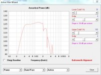
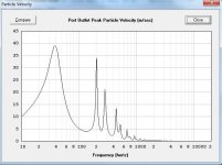
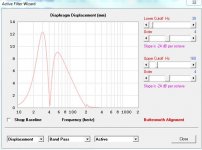
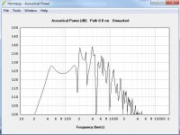
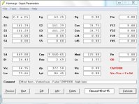
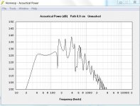
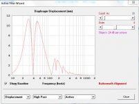
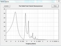
This is the best I could do. Based on the advice from just a guy (thanks). I am pretty happy with it. It doesn't play as high as I was originally hoping but it has a decent amount of output in the 40-150Hz range. Displacement looks good, but port velocity is high. Too high? I don't know.
Here are the specifics.
Drivers: 2 x Faital Pro 12HP1030
Construction: 3/4 inch Baltic Birch
Total internal box volume: 99.5 Liters (3.5 ft^3)
Slot port cross section: 12.5 x 2 inches (25 inches long)
Rear port cross section: 12.5 x 4 inches (33.25 inches long)
Here are the specifics.
Drivers: 2 x Faital Pro 12HP1030
Construction: 3/4 inch Baltic Birch
Total internal box volume: 99.5 Liters (3.5 ft^3)
Slot port cross section: 12.5 x 2 inches (25 inches long)
Rear port cross section: 12.5 x 4 inches (33.25 inches long)
Attachments
- Home
- Loudspeakers
- Subwoofers
- High SPL bass section for Wakeboard boat