I have never heard a good sub system in a boat period. It makes me think that a different approach is needed. eg. Trade some low frequency extension in for louder (somewhat higher) bass that can actually be heard.
Exactly.
In your position, I'd be thinking of pro audio 12" subs (the Kappalites look like they may be a good fit) in a ported box tuned to the lowest frequency you can live with (I'd suggest 42 Hz or upwards), and then EQ up the bottom end if needed. The response at frequencies most consider as "bass" should be loud enough to meet your needs.
What other speakers are you using on this boat, BTW?
Here is what is in the rest of the boat:
4 x wetsounds Pro80 - 8 inch pro audio mid bass driver with a co-axially mounted HLCD for the highs. These are powered by an Audison LRX 4 channel amp giving them an honest 900 watts. With 4 HLCDs these things are LOUD. They are mounted high on the wakeboard tower but without a big base section they dominate the frequency response.
4 x JL Audio 7.7 inch infinite baffle component marine speakers. These are great little speakers and very musical for a marine speaker. These 4 speakers share 600 watts and handle it very well. These are mounted in the sides of the boat in a IB setup firing directly into the cabin.
I like your suggestion but I can't do a standard ported box, There is nowhere to put it unless I just throw it in an enclosed locker and then I will loose a lot of SPL. I really need something that vents directly into the cabin without cutting 2 12 inch holes in the fiberglass. The locker I would like to use already has a 10 inch hole in it from where the stock sub was mounted. I would like to make use of that locker and that hole even if I have to make that hole a bit bigger or square eg. I want the vent from the box to line up exactly with the hole in the locker.
Yeah, it will be loud if you stick your head in the subwoofer box. At the end of a ski rope you can have a 12" clattering against the backplate and you'll barely be able to hear it over the engine. Subtract about 45dB from 'peak calculated' SPL to get real world in open space at 100 feet. A ski rope is 35 to 70, depending on how good you are. Shorter and it's harder to get around bouys or get much air. Without more cubic footage to work with, you'll probably have to compromise on extension.
The tunes are not for the people outside the boat. The guy at the end of the rope isn't going to hear anything unless you put a full size PA system on the boat.
Anyway, tune higher if you want, but how do you propose getting enough power to get the subs louder than I've shown? My sim is at 2200 watts, already double the power the OP's amp has, and if you tune higher you need even more power to get the extra deebeez, and you need drivers that can handle that extra power. Even if you load the boat up with batteries and amps, where are going to find drivers that can handle it?
I don't think it's practical at all to build a system to entertain the guy that's skiing, it's not going to happen, especially not in the space allotted for subs and the amp he already has.
One last thing, the amp OP has only has a non adjustable hpf with the highest setting of 30 hz. Tuning higher than 30 hz means the hpf won't be effective and you might as well not have a hpf at all. So you need MORE electronics if you want a hpf, or you risk destroying the drivers. I don't think these are a soft bottom driver like some pro drivers with a suspension that won't allow the driver to reach xlim, I think I remember somebody saying they WILL hit the limits hard.
There's a lot of things to consider when choosing a box tuning, these are just a few of them that I consider when making my recommendation, the frequency response of the media is another as I mentioned, and there's more too that I haven't mentioned, but these are the important ones.
Last edited:
Here is what is in the rest of the boat:
4 x wetsounds Pro80 - 8 inch pro audio mid bass driver with a co-axially mounted HLCD for the highs. These are powered by an Audison LRX 4 channel amp giving them an honest 900 watts. With 4 HLCDs these things are LOUD. They are mounted high on the wakeboard tower but without a big base section they dominate the frequency response.
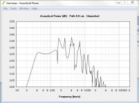
Based on the specs they gave, it looks like they're good for about 96dB/1W/1M in total. That should be the "benchmark" for your subwoofer design. And their "20Hz ~ 20kHz" rating is good only for a good chuckle. I'd be surprised if they even extend to 100 Hz (which is another "benchmark" for your subwoofer design - how far *up* the spectrum it needs to reach).
No wonder your JL Audio sub didn't make it. It's nowhere near that first benchmark
As for the vented box design, look at post #15. You're quite close there to what I'm thinking. Narrow the slot above the woofers a bit, and extend it down the side. There's your "vented box"
. Use HornResp to sim the results.Just to be clear (and fair) you can get a few db more by raising the tuning, up to 5 db more than I showed by raising it to 50 hz, with the same 2200 watts (and up to a couple db more if more power was available). So that's almost but not quite a doubling of sound intensity with a tradeoff of 20 hz of low extension.
That's not worth it in my opinion but to be fair it is something to consider IF the OP has a plan to get a working hpf that will work with a 50 hz tuning into the mix and doesn't mind missing the bassline on most of the songs.
When I showed my sim it was what I considered to be a reasonable compromise of several different factors, but it obviously shouldn't be considered the only correct answer. There's a lot of room for flexibility depending on which factors are most important.
As for the vented box design, look at post #15. You're quite close there to what I'm thinking. Narrow the slot above the woofers a bit, and extend it down the side. There's your "vented box"
I am not sure I understand. Are you thinking something like this?
Attachments
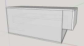
A little update. I have been working with the following concept. What do you guys think? Here are the details
Slot area = 100cm2 length = 68cm
port area = 188cm2 length = 82cm
rear chamber volume = 50 liters
driver Fatalpro 12hp1030 - 2 drivers parallel with 1000watts total
Did I simulate it correctly?
I am worried a bit about the size of the port and the slot being too small and causing wind noises. I am not sure how to calculate port velocity and even what an acceptable parameter is.
Attachments
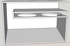
A little update. I have been working with the following concept. What do you guys think?
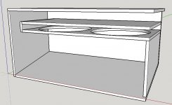
1. Remove that center board, and extend the vent a bit further into the enclosure
2. Sim as a TH with a large rear chamber and L12-L34 = vent length and S1:S4=vent cross-section area.
A little update. I have been working with the following concept. What do you guys think? Here are the details
Slot area = 100cm2 length = 68cm
port area = 188cm2 length = 82cm
rear chamber volume = 50 liters
driver Fatalpro 12hp1030 - 2 drivers parallel with 1000watts total
Did I simulate it correctly?
I am worried a bit about the size of the port and the slot being too small and causing wind noises. I am not sure how to calculate port velocity and even what an acceptable parameter is.
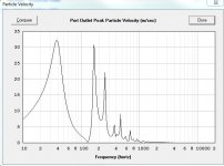
Yeah, at 188 sq cm you should be very worried about port noise and compression. Are you using Hornresp? Check velocity by going to Tools - Output - Horn and then Tools - Particle Velocity. You can dramatically reduce velocity by adding a small flare at the end of the port. Just a 45 degree chamfer at the end. The bigger you make it the lower velocity will go. I can check your core port velocity with Flare it (or you can do that) but not tonight.
If you post up your Hornresp inputs I can check it all over for you.
But until you get Audacity auditioned and figure out what tuning you actually want you probably should hold off on the box design. Spend the time in Audacity, not Sketchup.
1. Remove that center board, and extend the vent a bit further into the enclosure
2. Sim as a TH with a large rear chamber and L12-L34 = vent length and S1:S4=vent cross-section area.
I already did that, you get a big smiley face response curve with a huge dip in the middle, and big spikes at both ends of the bandwidth. Also bandwidth doesn't extend very high, nowhere near 200 hz.
There's an infinite number of variables so you might have better luck than I did but a quick first pass didn't look very promising.
Yeah, at 188 sq cm you should be very worried about port noise and compression. Are you using Hornresp? Check velocity by going to Tools - Output - Horn and then Tools - Particle Velocity. You can dramatically reduce velocity by adding a small flare at the end of the port. Just a 45 degree chamfer at the end. The bigger you make it the lower velocity will go. I can check your core port velocity with Flare it (or you can do that) but not tonight.
If you post up your Hornresp inputs I can check it all over for you.
But until you get Audacity auditioned and figure out what tuning you actually want you probably should hold off on the box design. Spend the time in Audacity, not Sketchup.
OK I will spend some time with Audacity.
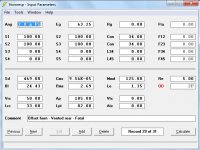
Yes I am using hornresp, thanks for the tip. I checked port velocity and the horn peaks around 40m/s at around 50Hz. The port gets to around 40m/s too but near 30hz where I will have my HP filter set. I'm still not sure if I am simulating the drawing correctly though so this could be wrong.
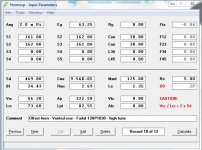
Here are the inputs I am using.
Attachments
OK I will spend some time with Audacity.
Yes I am using hornresp, thanks for the tip. I checked port velocity and the horn peaks around 40m/s at around 50Hz. The port gets to around 40m/s too but near 30hz where I will have my HP filter set. I'm still not sure if I am simulating the drawing correctly though so this could be wrong.
Here are the inputs I am using.
I only have time for a quick glance but it looks good except for Lrc. Set Lrc to the length of the longest dimension of the rear chamber. It's 33 now, it needs to run the entire length of the box.
When you get the design finalized I can run it through Akabak and fine velocity with the high pass filter in place. Maybe run it through Akabak with a flared port too.
Velocity is ideally 10 m/s or less, but that can lead to unreasonably large ports. Some people compromise with higher velocity, I'd never ever go above 27 for any reason and ideally I like to keep it at 10 or less. It shouldn't be too hard with flared ports.
OK so here is where I am at.
I have ordered 2 Faital Pro 12HP1030 drivers. Should arrive in a week or so. Of all the woofers I tried were pretty close to the best for my application. To top it off they have some weatherproofing treatment that should make them more suited to a boat.
I am trying to put the finishing touches on the design so I can start building when they arrive. Here is what I have so far:
Questions:
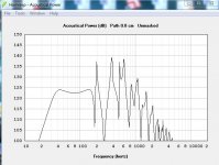
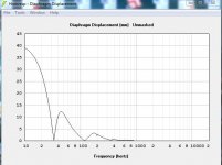
1. The high frequency response gets quite ugly above 150hz or so. Should I be concerned about this? I would like to cross over as high as possible
2. The port velocity is very high, do you think this is going to be livable?
3. How do I correctly measure the lenght of the port in the drawing I submitted? For the simulation I basically measured the length down the middle of the port, around the 90 degree bend, until it intersected with the rear chamber. Is this correct?
4. the high frequency response gets a bit better if I choose "mask rear chamber resonances" Is there anything I can do when I build the box to mask these resonances? eg. Line the walls?
I have ordered 2 Faital Pro 12HP1030 drivers. Should arrive in a week or so. Of all the woofers I tried were pretty close to the best for my application. To top it off they have some weatherproofing treatment that should make them more suited to a boat.
I am trying to put the finishing touches on the design so I can start building when they arrive. Here is what I have so far:
Questions:
1. The high frequency response gets quite ugly above 150hz or so. Should I be concerned about this? I would like to cross over as high as possible
2. The port velocity is very high, do you think this is going to be livable?
3. How do I correctly measure the lenght of the port in the drawing I submitted? For the simulation I basically measured the length down the middle of the port, around the 90 degree bend, until it intersected with the rear chamber. Is this correct?
4. the high frequency response gets a bit better if I choose "mask rear chamber resonances" Is there anything I can do when I build the box to mask these resonances? eg. Line the walls?
Attachments
1. It's not ideal but a bit of stuffing could help a bit. In reality really sharp spikes and dips won't be present in your measurement of the finished product but those spikes are pretty wide, they aren't going anywhere without damping. You have to figure out which part of the box is producing the resonances and damp it. It's probably a combination of the backside and frontside. Damping the frontside will just accumulate moisture, not sure how viable that will be.
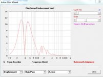
2. If you are actually going to use the high pass filter as shown in the 3rd pic that will knock the velocity down a bit. Maybe by as much as half.
3. Straight down the center is fine, right from the part where it joins into the bigger part of the box to the end. Not sure if Hornresp calculates end correction for segments, probably not, so you could add a couple inches to that.
4. Yes, damping. That's all you can really do short of a complete redesign. Hornresp can simulate damping, not sure if that applies to this type of enclosure or not.
How are you going to install and maintain the drivers? Is there an access panel?
1. It's not ideal but a bit of stuffing could help a bit. In reality really sharp spikes and dips won't be present in your measurement of the finished product but those spikes are pretty wide, they aren't going anywhere without damping. You have to figure out which part of the box is producing the resonances and damp it. It's probably a combination of the backside and frontside. Damping the frontside will just accumulate moisture, not sure how viable that will be.
2. If you are actually going to use the high pass filter as shown in the 3rd pic that will knock the velocity down a bit. Maybe by as much as half.
3. Straight down the center is fine, right from the part where it joins into the bigger part of the box to the end. Not sure if Hornresp calculates end correction for segments, probably not, so you could add a couple inches to that.
4. Yes, damping. That's all you can really do short of a complete redesign. Hornresp can simulate damping, not sure if that applies to this type of enclosure or not.
How are you going to install and maintain the drivers? Is there an access panel?
How do I determine which part of the box is causing he resonances? Is there a tool in hornresp for that?
I have no plan for driver maintenance. As far as I can tell I am going to have to install the woofers as I make the box. That narrow slot is only 2 inches wide and the woofers will have to drop in from there. I know this is not ideal but I don't know a way around it.
glad to see this coming to fruition. also glad to see my "shoot from the hip" advice hit its mark
Ha yea it turned out pretty well indeed. I am pretty impressed at how little volume these woofers need. And to top it off they are treated for weather resistance. A little spendy once I get them to Canada but I think I am going to be happy.
- Home
- Loudspeakers
- Subwoofers
- High SPL bass section for Wakeboard boat