CrashHouse .. this site will answer all your questions
Power Supplies
Thanx!
I just connected positive to positive and neg to neg from the rectifier bridge to the big capacitor, then to the T4 power inputs. See pic.
The amp is on another level with the WIMAs gone. I am going to check out that youtube video.
And what cap did you use between the poles? Doesn't this impose a danger to exceed the max voltage?
And what cap did you use between the poles? Doesn't this impose a danger to exceed the max voltage?
Not sure about your question, but adding that big cap might add 1 volt or so to the equation. I am just over 50 VDC being measured at the T4 power terminals. The cap itself is rated for 60 VDC.
Not sure about your question, but adding that big cap might add 1 volt or so to the equation. I am just over 50 VDC being measured at the T4 power terminals. The cap itself is rated for 60 VDC.
I meant the black cap which is connected parallel to the + and - poles on you big blue capisitor.
Not sure about your question, but adding that big cap might add 1 volt or so to the equation. I am just over 50 VDC being measured at the T4 power terminals. The cap itself is rated for 60 VDC.
I meant the black cap which is connected parallel to the + and - poles on you big blue capisitor.
I meant the black cap which is connected parallel to the + and - poles on you big blue capisitor.
Oh, that one. It is a polypropylene bypass capacitor, it adds no voltage along with the other smaller one. I've seen it done by many, but how it affects sound, I don't know. Its effect is not as clear to me as bypassing the input capacitors, in which case I did A/B the sound.
Oh, that one. It is a polypropylene bypass capacitor, it adds no voltage along with the other smaller one. I've seen it done by many, but how it affects sound, I don't know. Its effect is not as clear to me as bypassing the input capacitors, in which case I did A/B the sound.
Oh okay thanks for the explenation...
Very nice! Are you using it as a power amp? How do you like those Mundorfs? at least compared to the WIMA.
yes i am using it as a power amp. That was the simplest way to connect it for me and i allready have a passive pre. REgarding the Mundorf caps, i really cant comare them to the Wima as my Mundorfs were fitted as standard.
Okay forgive me for being a noob, but I've got a question. While I'm waiting for my replacement T4 I thought to construct a simple rectifier so I could connect to DC instead of AC. This by using a 25A 50V rectifier and a couple of 22000uF 100V Philips caps I have. So I connected my 33V downsized toroid to the rectifier and attached three of the caps to the poles of the rectifier. Then I measured the voltage being 90V !!! Unloaded. Is this correct or am I forgetting something? Yes yes I'm a beginner with small steps in the wonderful world of DIY amps...
Okay forgive me for being a noob, but I've got a question. While I'm waiting for my replacement T4 I thought to construct a simple rectifier so I could connect to DC instead of AC. This by using a 25A 50V rectifier and a couple of 22000uF 100V Philips caps I have. So I connected my 33V downsized toroid to the rectifier and attached three of the caps to the poles of the rectifier. Then I measured the voltage being 90V !!! Unloaded. Is this correct or am I forgetting something? Yes yes I'm a beginner with small steps in the wonderful world of DIY amps...
Make sure you are measuring AC with AC Volts setting and DC with DC volts setting on the voltimeter and at the right place on the rectifier, AC where you see ~ and DC for + -
Perhaps...
Also, 33 v AC * 1.414 = 46.662 VDC, add maybe 1 volt for the caps if necessary, you should be about 47-48 volts rectified DC.
Yes I do but after the caps it gets this high! Are the caps building up the voltage near their max voltage capacity?
Can you post a picture of how you got things wire up and where you are measuring?
Can you post a picture of how you got things wire up and where you are measuring?
Okay I will do so tomorrow okay?
I am finally going to order a T4 amp to test with our high efficiency Klipsch speakers. If it works out okay I'll order 3 more to allow Active EQ on the 3 fronts in our 5.1 system.
Have a couple of questions.
1. There appears to be some kind of 'Molex' connector for input on the amp. Do they ship a matching connector and or some kind of plug/cable with the amp? I can't find any info on their website.
2. The amp doesn't have volume controls and I would like to add a volume control on each input (ganged).
A. Any idea what resistance pot to use? I'm driving the amps directly from an Asus Essence soundcard in our HTPC.
B. Might this addition have negative affects on the sound quality?
Thanks for any assistance.
Rod
")
Can you post a picture of how you got things wire up and where you are measuring?
Well I was about to take the picture but I measured on a couple of places and am confused now.
34VAC > ~ input rectifier side > + rectifier pole > + pole capacitors
0VAC(not used)
34VAC > ~ input rectifier side > - rectifier pole > - pole capacitors
So at the rectifier poles I measure 54 volts and at the last capacitor pole I measure about 90 volts.
Last edited:
Well I was about to take the picture but I measured on a couple of places and am confused now.
34VAC > ~ input rectifier side > + rectifier pole > + pole capacitors
0VAC(not used)
34VAC > ~ input rectifier side > - rectifier pole > - pole capacitors
So at the rectifier poles I measure 54 volts and at the last capacitor pole I measure about 90 volts.
I think you have the secondary (output wires) wires of the transformer hooked up wrong.
If you have dual secondaries (four wires), then the "0" wires should be on one ~ pole and the "34" on the other ~.
If you have one secondary (three wires) winding with a center tap "0", then this center tap must be on one ~ pole and the other 2 wires on the other ~ pole.
If NOT, then when you measure you would be capturing the additive voltage 34 + 0 + 34 = 68 VAC * 1.414 (rectification) = 96 + VDC.
But before you go blowing anything up, let someone confirm the above information.
1) There is a cable with the amplifier of course
2) No problem
3) 50K is what hifimediy is using with T1/T2 so it should do fine
Thanks very much for the information. Now I will order an amp.
Happy New Year everyone!!!
Rod
I think you have the secondary (output wires) wires of the transformer hooked up wrong.
If you have dual secondaries (four wires), then the "0" wires should be on one ~ pole and the "34" on the other ~.
If you have one secondary (three wires) winding with a center tap "0", then this center tap must be on one ~ pole and the other 2 wires on the other ~ pole.
If NOT, then when you measure you would be capturing the additive voltage 34 + 0 + 34 = 68 VAC * 1.414 (rectification) = 96 + VDC.
But before you go blowing anything up, let someone confirm the above information.
I have five wires. 2 times 34 VAC, 2 times 18 VAC and one 0 VAC.
So I have to wire the two 34 VAC together on one ~ pole and the 0 VAC to the other one?
I have five wires. 2 times 34 VAC, 2 times 18 VAC and one 0 VAC.
So I have to wire the two 34 VAC together on one ~ pole and the 0 VAC to the other one?
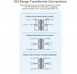
This may help, I use the Avel transformers and connect the secondaries together. Look at the top config in this photo, it may make it clear. It would help if you know the wiring configuration of your transformer.
Anyhow, don't hook up anything but the rectifier to it and get the correct voltage. This way you will not blow anything up.
Attachments
- Status
- This old topic is closed. If you want to reopen this topic, contact a moderator using the "Report Post" button.
- Home
- Amplifiers
- Class D
- Hifimediy T4 board