This may help, I use the Avel transformers and connect the secondaries together. Look at the top config in this photo, it may make it clear. It would help if you know the wiring configuration of your transformer.
Anyhow, don't hook up anything but the rectifier to it and get the correct voltage. This way you will not blow anything up.
Fuse blown...

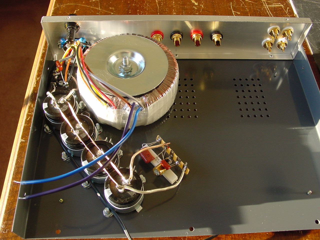
Here is a dual primary and dual secondary Avel transformer. Notice the rectifier bridge barely visible to the left of the transformer. The four wires to the right coming out of the transformer are the primaries, gray and brown go to one mains wire, the blue and purple go to the other mains wire. The other four wires to the left of these are the output or secondaries. Refer to the schematic I posted earlier about this Avel transformer. Both the primaries are connected together, and both the secondaries are connected together.
On the output wires or secondaries, there are dual windings, one is the black and red, the other winding is the yellow and orange (see earlier schematic). Notice that these are connected on opposite sides of the ~ rectifier bridge poles. If I were to connect black and red on the same ~ pole for example, I would short out that winding. Likewise, if I connect yellow and orange on the same ~ pole, I would short out that winding.
Hope this helps. Can you get a schematic of the transformer somewhere?
Last edited:
Well modified the toroid, removing a couple of windings. I was thinking about the nedt setup using two rectifiers, splicing the 0 volt wire. Use one 0 VAC with one 31.5 VAC on one rectifier and another 0 VAC with the other 31.5 VAC. Then each one to the big caps making aboutb 45 VDC each. Is it possible to combine the two to get the maximum current and thus power?
Connecting T4 and SMPS300R
I recently got the HifimeDiy T4 amp and Connex SMPS300R 48v.
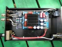
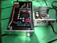
When googling for how to connect these, I cam across 2 project where the owners had posted pictures of the wiring. I am attaching 2 such pics.
One project is with a volume pot, and the other without.
I guess they must have done it properly as they seemed happy with their amps, but it does not hurt to check!
Can anyone please confirm if the wiring shown in the pics below is ok?
Also, any suggestions on the potentiometer value in case I want to connect one?
Thanks,
Zia
I recently got the HifimeDiy T4 amp and Connex SMPS300R 48v.
When googling for how to connect these, I cam across 2 project where the owners had posted pictures of the wiring. I am attaching 2 such pics.
One project is with a volume pot, and the other without.
I guess they must have done it properly as they seemed happy with their amps
, but it does not hurt to check!Can anyone please confirm if the wiring shown in the pics below is ok?
Also, any suggestions on the potentiometer value in case I want to connect one?
Thanks,
Zia
Attachments
Last edited:
I recently got the HifimeDiy T4 amp and Connex SMPS300R 48v.
When googling for how to connect these, I cam across 2 project where the owners had posted pictures of the wiring. I am attaching 2 such pics.
One project is with a volume pot, and the other without.
I guess they must have done it properly as they seemed happy with their amps
Can anyone please confirm if the wiring shown in the pics below is ok?
Also, any suggestions on the potentiometer value in case I want to connect one?
Thanks,
Zia
Hi zman01,
Please read alkasal's post with a diagram for SMPS300R to T2 connection. It can for your reference.
http://www.diyaudio.com/forums/class-d/164274-new-tk2050-board-197.html
Hifimediy T1 and T2 boards are using 50k potentiometer, I think you can use this value for the T4.
Well modified the toroid, removing a couple of windings. I was thinking about the nedt setup using two rectifiers, splicing the 0 volt wire. Use one 0 VAC with one 31.5 VAC on one rectifier and another 0 VAC with the other 31.5 VAC. Then each one to the big caps making aboutb 45 VDC each. Is it possible to combine the two to get the maximum current and thus power?
Hi CrashHouse,
I think the secondary output in your transformer will be like this; 34-0-34 and 0-18. You can check the wire/colour code label printed in the size of the transformer.
you can use "Full-wave rectifier, center tapper design" to produce above 34*1.41-2Vof rectifier dull~=45VDC for the T4.
Rectifier circuits : DIODES AND RECTIFIERS
Hi zman01,
Please read alkasal's post with a diagram for SMPS300R to T2 connection. It can for your reference.
http://www.diyaudio.com/forums/class-d/164274-new-tk2050-board-197.html
Hifimediy T1 and T2 boards are using 50k potentiometer, I think you can use this value for the T4.
Thank you Cronm for the link.
I also noticed that the SMPS300R has an aux power connector - according to the manual this is good for 10.5-13v range. I have a VC23 preamp board - would I bel able to connect the board from this aux connector - the board takes 12 VAC. the other option is use a AC-AC power brick/adapter - I have one rated at 12VAC and 1000mA - that should be fine for VC23?
Regarding volume pot, will go for a decent Alps one I think. Will come in handy if I choose to use the preamp elsewhere.
Hi CrashHouse,
I think the secondary output in your transformer will be like this; 34-0-34 and 0-18. You can check the wire/colour code label printed in the size of the transformer.
you can use "Full-wave rectifier, center tapper design" to produce above 34*1.41-2Vof rectifier dull~=45VDC for the T4.
Rectifier circuits : DIODES AND RECTIFIERS
Yes i checked and have two (modified) 31 volt leads, two 18 volt lead and one 0 volt lead. So if I only use one 31 volt lead with the 0 volt lead and rectify it this would make about 44 volt DC. But my main concern is would I make use of the maximum power of the 500 watt toroid if I don't use the other leads?
Thank you Cronm for the link.
I also noticed that the SMPS300R has an aux power connector - according to the manual this is good for 10.5-13v range. I have a VC23 preamp board - would I bel able to connect the board from this aux connector - the board takes 12 VAC. the other option is use a AC-AC power brick/adapter - I have one rated at 12VAC and 1000mA - that should be fine for VC23?
Regarding volume pot, will go for a decent Alps one I think. Will come in handy if I choose to use the preamp elsewhere.
I think the VC23 preamp board is also came from Hifimediy. I don't know it. But from the picture of the board in Hifimediy webset, the board has it's own rectify and reguration circuits. You should check with Hifimediy that will this board allow direct DC input from the SMPS300R and the input voltage.
Also, the preamp board looks like "+ 0 -" AC input for rectification. First, is your transformer provide 2 x 12V AC output? Secondly, Hifimediy provide 2 x 9V AC PSU for the his preamp boards. I don't know will 2 x 12V AC input too high for the board. Check with Hifimediy to confirm the maximum AC input voltage.
Since the preamp has remove volume control, I think you don't need another volume control for the T4 board.
Yes i checked and have two (modified) 31 volt leads, two 18 volt lead and one 0 volt lead. So if I only use one 31 volt lead with the 0 volt lead and rectify it this would make about 44 volt DC. But my main concern is would I make use of the maximum power of the 500 watt toroid if I don't use the other leads?
I think your transformer has 2 secondly AC output groups: the 1st group is 31-0-31, the 2nd group is 0-18. It is better if you can post the wire/colour code label to confirm.
You cannot use only one 31 volt land with the 0 volt lead to rectify a 44 volt DC. This is a Half-wave rectify and just provide half voltage. You should use both 31 volt leads and 0 volt lead to set up a Full-wave rectifier to product about 44VDC and fully utilize the maximum power of the transformer.
Hello everyone.
I'd like to know if the T4 board has a speaker protection against DC current.
I don't mean power on delay to prevent tump; I mean the detachment of the speakers in case a failure of the PSU or the T4 board could cause a DC current flow into the speakers.
I think that the phrase:
*Speaker protection: DC/error and power on delay, power down immediately off (when transformer powered)"
gave an answer to my question. But I'd like to have a confirmation from T4 owners.
Thank you very much.
I built the power amp (without pot), working fineI recently got the HifimeDiy T4 amp and Connex SMPS300R 48v.
Can anyone please confirm if the wiring shown in the pics below is ok?
Thanks,
Zia
I am going to buy some of the Mundorf Supreme caps as suggested. I note that you have changed the value of the original input capacitors from 2.2 uf to 5.6 uf. is there any befefit to this?Get a couple of Mundorf M Supreme Caps.
I am going to buy some of the Mundorf Supreme caps as suggested. I note that you have changed the value of the original input capacitors from 2.2 uf to 5.6 uf. is there any befefit to this?
Not really, I just happen to have those available. Some manufacturers go as high as 10 uF. Most commonly you see 2.2 or 3.3 uF.
I guess whaleman has moved the input high pass frequency from 1,4Hz to 0,5HZ...ghgh [if Z-in is 50kohm...]. Not really important...the other values are more important..have a look at this
That is a great link on capacitors, thanks for sharing. The Mundorf M Supremes rank high in my opinion and did in theirs as well.
Aaaarrggggg!!!
Friedmy T4 again.
Well I thought to go the safe route. I used one 31 VAC and the 0VAC lead to rectify to 44 VDC. I spliced the )VAC lead to use it with a 18 VAC lead and stept it down to 12VDC 1A. All things went well and when I connected the 44VDC the T4 turned on like it should.
But things got bad when I connected the preampwith the stepped down 12VDC. The 44VDC rose to about 67VDC and fried the damn thing. I ordered a new T4 (without the Mundorfs cause I used Jantzen Superior Z 2.2uF caps but don't want to gothis route again. I have a small 12VDC 1A SMPS to power the tube preamp, but I'd like to know what I did wrong.Cause DIY is about learning too isn't it?
Friedmy T4 again.
Well I thought to go the safe route. I used one 31 VAC and the 0VAC lead to rectify to 44 VDC. I spliced the )VAC lead to use it with a 18 VAC lead and stept it down to 12VDC 1A. All things went well and when I connected the 44VDC the T4 turned on like it should.
But things got bad when I connected the preampwith the stepped down 12VDC. The 44VDC rose to about 67VDC and fried the damn thing. I ordered a new T4 (without the Mundorfs cause I used Jantzen Superior Z 2.2uF caps
but don't want to gothis route again. I have a small 12VDC 1A SMPS to power the tube preamp, but I'd like to know what I did wrong.Cause DIY is about learning too isn't it?An externally hosted image should be here but it was not working when we last tested it.
Last edited:
- Status
- This old topic is closed. If you want to reopen this topic, contact a moderator using the "Report Post" button.
- Home
- Amplifiers
- Class D
- Hifimediy T4 board