jamesrnz said:steve,
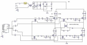
i found the pfc schematic i was looking for. it was posted be cocoholic.
i sent him an email with no answer back yet.
i have attached his scchematic.
and was wondering why the 1n5407 across the boost inductor?
jimbo
Eva said:The diode across the boost inductor is only employed during startup. It prevents excess energy from being stored in the inductor and then dumped back to the output capacitors, as too much energy is likely to be transferred, thus causing an overvoltage condition.
Back again...
This diode can only partially avoid the start up resonance and eventually overvoltage. The effect which Eva describes is not only caused by the chokes in our circuits. The chokes in our circuits cannot store much energy due to saturation effects. The energy from them will normally just cause minor overshoot. Unfortunately the mains also has an inductance, which can store huge amounts of energy and cannot be bypassed by a diode. Especially with a soft power line and unpleasant phase angle of powering up - there can happen a remarkable voltage overshoot at the output of most boost converters. Hard powerlines are less critical because the resulting Q of the undesired resonance is lower then.
(In anddition to this overshoot, some topologies are suffering from some 'self made' active overshoot, caused by unfortunate regulation behaviour.)
There is another reason for me to put this diode.
Our power lines do show impressive voltage spikes once and a while. They can cause stress and defect to the MosFet. The diode across choke+PFCdiode is clamping such overvoltage surges vs the output caps, which can absorb quite some energy without excessive voltage change.
In European immunity standards there are surge tests with 1kV(symmetrical) ... 2kV(unsymetrical) defined. ...some 9uF cap charged to that voltage and then coupled with some single Ohms to the input of the unit under test, which is driven by a line with standardized impedance...
In US there are similar UL regulations.
I.e. 6kV ring wave test. Please note. The 6kV ring wave is less stressy than the European test, because the energy in the UL test is by less than in the European 2kV test.
I forgot to mention:
After I have built this beast and got it running, I would very clearly agree to Eva... At the beginning of my project she advised me to consider continous mode, in order to avoid high peak currents.
I was stubburn enough to go for 1kW with critical conduction mode and finally got it running in a proper manner. Originally I thought it would be just a question of proper (and my be slightly expensive MosFet choice) But proper MosFet turn OFF and snubbering was more tough than expected. So this design is touching the limit of any reasonable consideration, or might be already beyond.
From my perspective, I would say that at 230V you should consider continuous mode above 500W. At 120V already above 250W.
After I have built this beast and got it running, I would very clearly agree to Eva...
At the beginning of my project she advised me to consider continous mode, in order to avoid high peak currents.I was stubburn enough to go for 1kW with critical conduction mode and finally got it running in a proper manner. Originally I thought it would be just a question of proper (and my be slightly expensive MosFet choice) But proper MosFet turn OFF and snubbering was more tough than expected. So this design is touching the limit of any reasonable consideration, or might be already beyond.
From my perspective, I would say that at 230V you should consider continuous mode above 500W. At 120V already above 250W.
Consider splitting the 400V to 450V output from the PFC in two 200V to 225V halves by means of a capacitive divider, and using a half-bridge converter instead. Given the same output power, current requirements will be similar to those of a full bridge fed with rectified mains since in the latter case you have to account for low line conditions and higher voltage ripple, resulting also in a 200V to 250V minimum supply.
BTW: Choco you are just nice. Have you checked my new MOSFET+IGBT switching approach?
BTW: Choco you are just nice. Have you checked my new MOSFET+IGBT switching approach?
Eva said:
BTW: Choco you are just nice. Have you checked my new MOSFET+IGBT switching approach?
Sorry, no idea so far.
During the last three weeks I only checked my girl friend and Down Under. Not so bad
 .
.Sydney, Outback, East Coast, outer Barrier Reef scuba diving (...amazing corals and fish.. ..found a giant turtle during a night dive !)..
Definitely one of my best holidays

Starting to envy the Aussies!
...but now... GAME OVER.. ...crazy working again...
I will search the forum for your MOS+IGBT approach.
What a holiday, you are making me jealous!! (Did I mention that I'm developing stuff for an Australian company? I will have to take their offers more seriously! )
BTW: http://www.diyaudio.com/forums/showthread.php?s=&threadid=88740
)BTW: http://www.diyaudio.com/forums/showthread.php?s=&threadid=88740
You really should take such offers serious.
...grow with the company.... may be go to Australia for some years...
Sorry Jimbo for OFF TOPIC (feel free to let remove this posting, but I cannot resist...):
Up to now I just found three spots in the world, where I really could imagine to live a happy life for longer time.
- Germany, especially Munich.
- USA, San Francisco area is nice and offering good job opportunities. May be New York.
- Down Under. Sydney area is offering the perfect combination of urban life, and immediate holiday feeling if you go to some beach....
...looks like am addicted to larger cities...

Jimbo:
I like EVA's approach to half-bridging the output of the PFC. I did it in my prototype shown: 2- 560mF 250V Panasonic TSNH low-ESR 105C caps in series, balanced by two 100kW 2W resistors.
From that point, your half-bridge converter will be the same as a non-PFC'ed SMPS with the following exceptions: 500-600V MOSFETs or IGBTs, Main Xfmr Primary now calculated for 385-400VDC, and main rectifiers rated for atl east 800PIV.
The PFC I posted is critical-conduction circuit, and is rated at 180W. The PFC chip is an MC33262 driving an MTW20N50E into a PFC coil by Coil Craft designed specifically to work with this chip. Before I knew anything about this forum or any of the excellent advice by EVA and the other usual suspects, I did the mains rectifiers and Boost Diode with MUR8100s.
I really need to invest in a good Variac with isolation, as I am
reluctant to power it back up since it blew a 5A fuse when I first powered it up 6-7 years ago.
Steve
I like EVA's
approach to half-bridging the output of the PFC. I did it in my prototype shown: 2- 560mF 250V Panasonic TSNH low-ESR 105C caps in series, balanced by two 100kW 2W resistors.Eva said:Consider splitting the 400V to 450V output from the PFC in two 200V to 225V halves by means of a capacitive divider, and using a half-bridge converter instead. Given the same output power, current requirements will be similar to those of a full bridge fed with rectified mains since in the latter case you have to account for low line conditions and higher voltage ripple, resulting also in a 200V to 250V minimum supply.
From that point, your half-bridge converter will be the same as a non-PFC'ed SMPS with the following exceptions: 500-600V MOSFETs or IGBTs, Main Xfmr Primary now calculated for 385-400VDC, and main rectifiers rated for atl east 800PIV.
The PFC I posted is critical-conduction circuit, and is rated at 180W. The PFC chip is an MC33262 driving an MTW20N50E into a PFC coil by Coil Craft designed specifically to work with this chip. Before I knew anything about this forum or any of the excellent advice by EVA and the other usual suspects, I did the mains rectifiers and Boost Diode with MUR8100s.
I really need to invest in a good Variac with isolation, as I am
reluctant to power it back up since it blew a 5A fuse when I first powered it up 6-7 years ago.
Steve
steve
i am collecting pfc parts right now.
i will simplify my full bridge and get i running before the pfc happens.
we live in a agircultural community near grain elevators, which have huge line transients, with lifting motors, auger motor, grains dryers and such.
i have watched the current and voltage on the lines coming into the house and lets just say they are interesting. i have put large movs on the mains and sometimes they get warm................
jimbo
well,
i have found that in the full bridge that i iam blowing one of the pairs apparently due to some thing turning on the opposite pair.
some things.
i am using gate drive with zeners caps and transformer. simple.
i read about fets on the same heat sink can cause turn on of the opposite pair.
i wonder if the turn on is caused be the toriod interfering with the 33025.
i wonder if the schottky output bridge is causing problems, i donthink so.
jimbo

Your gate drive is all wrong. The 10 ohm and 100 ohm gate resistors must be swapped with respect to what is shown in the schematic. Also, a DC bleeder resistor (say 1K) must be connected in the secondary side of each gate transformer, between the right leg of the 0.1 capacitor and the lower leg of the winding.
Note that you could do it better with a single gate transformer with 4 secondaries and a single primary connected between OUT_A and OUT_B. Adding turn-off buffer transistors to each gate drive cell would be another great improvement.
Note that you could do it better with a single gate transformer with 4 secondaries and a single primary connected between OUT_A and OUT_B. Adding turn-off buffer transistors to each gate drive cell would be another great improvement.
- Status
- This old topic is closed. If you want to reopen this topic, contact a moderator using the "Report Post" button.
- Home
- Amplifiers
- Power Supplies
- hi power smps