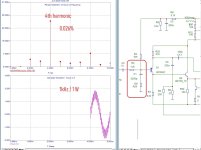
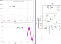
I decided on a filter/supply voltage stabilizer circuit for the unipolar version.
The filter circuit in the attachment is essentially a small board with three terminals 1 - + power supply, 2 - output to Radd, 3 - minus input from the rectifier.
The rectifier itself is made “isolated” relative to the gnd.
The power transistor used IRF3710 (max current 59A)
capacitors C2 and C4 are of small ratings, because large ratings interfere with the operation of the stabilizer filter and distort the shape of the ripples on the load.
Instead of diodes, I installed an LED to make it convenient to see that the power is on.
The ripple suppression coefficient is -47dB at a load of 2.5A, the ripple shape is almost sinusoidal. This electronic stabilizer filter is enough to connect two amplifier channels simultaneously.
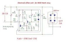
if instead of an electronic filter you use a passive filter C=22000 μF + R=0.18 ohm + C=22000 μF, then with a load of 1.3 A only -12 dB is filtered and the ripple shape will be like a distorted sine wave. This means that for two channels it is advisable to use two separate such CRC filters.
The filter circuit in the attachment is essentially a small board with three terminals 1 - + power supply, 2 - output to Radd, 3 - minus input from the rectifier.
The rectifier itself is made “isolated” relative to the gnd.
The power transistor used IRF3710 (max current 59A)
capacitors C2 and C4 are of small ratings, because large ratings interfere with the operation of the stabilizer filter and distort the shape of the ripples on the load.
Instead of diodes, I installed an LED to make it convenient to see that the power is on.
The ripple suppression coefficient is -47dB at a load of 2.5A, the ripple shape is almost sinusoidal. This electronic stabilizer filter is enough to connect two amplifier channels simultaneously.

if instead of an electronic filter you use a passive filter C=22000 μF + R=0.18 ohm + C=22000 μF, then with a load of 1.3 A only -12 dB is filtered and the ripple shape will be like a distorted sine wave. This means that for two channels it is advisable to use two separate such CRC filters.
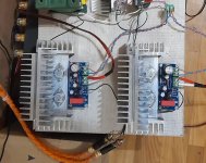
So I assembled 2 channels and connected them now and am listening.
The input filter has been adjusted to ensure minimal IMD distortion.
To adjust the BIAS, I added trimmers in parallel with resistor R11 (27 ohms)
The left and right channel amplifier blocks are connected through one power supply, taking into account the electronic filter/stabilizer, which I consider necessary.
Attached is a photo of a working layout and the actual circuit of the amplifier. The circuit of the electronic filter is higher in the post.
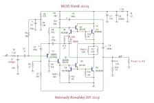


From the initial topology, probably only the resistor R5 = 8.2 kOhm remains; it determines the linearity of the gain of the input transistor.Hennady it could be fun if you highlight the original part of the circuit in another color along with original part. -When its final off course.
Now I’m listening to the assembled amplifier - I’m very pleased with the sound, good soundstage, wide stereo base, reverberation (echo) on compositions is more audible, light powerful sound - volume slider at 20%, dense clear Punch Bass, soft highs. It will become clearer after comparative listening tests.
Thanks for the tip on adjusting the compensation for IMD distortions.Cheers!
Hello everyone who is interested in the topic!
Due to illness, work slowed down a little.
But I was able to finish the electronic supply voltage filter and now the design looks like this:
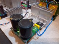
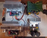
Also a question for the owners of JLH amplifiers, do you also reproduce them with such a pronounced “echo” effect?
Due to illness, work slowed down a little.
But I was able to finish the electronic supply voltage filter and now the design looks like this:


Also a question for the owners of JLH amplifiers, do you also reproduce them with such a pronounced “echo” effect?
Did I understand correctly that we are talking about a composite?I'm hoping you will get back to your op-amp version you mentioned a few posts back. Very interesting concept.
I modeled this option, the main thing is linearity in the audio frequency band and the absence of electrolytic capacitors, except for the tracking load in the driver - it should not be removed or replaced with a stable current generator, because The maximum output power is reduced.
a milked operational amplifier TL072 was used, its gain of 30 dB was made as linear as possible due to the R8C5 circuit.
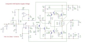
Few questions regarding the composite amp:
1) Servo is actually needed? I guess it is, with this single device input instead of LTP...
2) If we replace 2N3055 with some more decent devices, will this improve the amp?
3) Can we increase rails to say 25V, and power op-amps via 15V Zeners?
1) Servo is actually needed? I guess it is, with this single device input instead of LTP...
2) If we replace 2N3055 with some more decent devices, will this improve the amp?
3) Can we increase rails to say 25V, and power op-amps via 15V Zeners?
Initially, the purpose of the serv was to exclude the capacitor in the circuit of resistor R5, because in this circuit such the capacitor increases the level of distortion at mid frequencies. Such distortions can be combated by endlessly only increasing the capacitance of this capacitor. Also in the circuit there is a circuit of local NFB R6C5, thanks to it the negative influence of the servo is not noticeable, neither in phase nor in frequency.1) Servo is actually needed? I guess it is, ...
Balance compensation R13C8 has finally been introduced into the JLH circuit; with it, the frequency properties of the output transistors no longer affect the parameters of the circuit))), so use any modern transistors.2) If we replace 2N3055 with some more decent devices, will this improve the amp?
The issue with powering the operational amplifier from the zener is ok, no problem there. But the supply voltage of +/- 25 volts for the output stage is more serious. Those. At this supply voltage, at least 3 pairs of output power transistors are required.3) Can we increase rails to say 25V, and power op-amps via 15V Zeners?
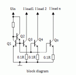
Precision assemblies Q3Q4Q7 and Q5Q6Q8 assume theoretically infinite parallelization of Q7 and Q8, respectively. Therefore, you can parallelize without problems (patent).
Last edited:
??Also a question for the owners of JLH amplifiers, do you also reproduce them with such a pronounced “echo” effect?
When soundrecording speech, singing, music, the use of artificial reverberation is an integral part of the overall processing and sound recording of the audio signal. Reverberation is used to improve the clarity of speech, singing and the sound of individual musical instruments.
This amplifier produces a crisp and clear Echo/Reverb effect that enhances the sound quality of a music program and is subjectively very audible.
I have a guess that the reason is the electronic supply voltage filter.
In a modified version of the circuit, Mosfets can be used as power transistors.
What additions:
*The supply voltage must be increased to 36 volts,
*Additionally use a stable current generator in the driver load, i.e. Mosfets are voltage controlled; they have no internal local feedback - it is necessary to eliminate the dependence of the initial current on the supply voltage.
* Move the feedback resistor to the output of the amplifier to control symmetry, for the same reason as in the previous paragraph
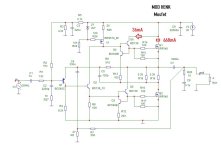
- The initial current of power transistors may be less, because it is the power dissipation that is important and not the value of the initial current, here it is 668 mA.
- I also lowered the HF cutoff frequency at the amplifier input to reduce IMD distortion.

I believe any echo/reverb is proof of a faulty design sorry. You must have unintentionally have made part of your circuit produce a delay. Multiple short delays sound as reverb.
If you can identify and isolate the cause, you may have a valuable patent for use in musical instruments 🫢. Small amounts of reverb and delay may improve the musical enjoyment of a stereo-system and I think most midd level brands sold such processors to ad between pre out/main in or in tape loop early 80ies.
Cheers!
Maybe the "reverb" is just more audible, not lost in noise or distorsion? Sound impressions are subjective descriptions of personal perception.I believe any echo/reverb is proof of a faulty design sorry.
You misunderstood my question.I believe any echo/reverb is proof of a faulty design sorry.
I'm not talking about a device that generates reverberation, but about an amplifier that better conveys this effect already recorded on the medium.
Do you have an approximate idea of the delay time constant for generating a reverb effect? Can you show such a circuit in the diagram?You must have unintentionally have made part of your circuit produce a delay. Multiple short delays sound as reverb.
My assumption was that there was an electronic filter, the circuit is such that it filters odd harmonics in the power supply, because the control transistor takes the signal from a symmetrical divider. And, by the way, the ripple shape at the output of the electronic filter is practically a sinusoid, unlike, for example, a CRC filter.
What kind of bias do you have towards reverberation - its main purpose is to increase speech intelligibility, which is probably why it was used by advertisers and not only in the 80s..Small amounts of reverb and delay may improve the musical enjoyment of a stereo-system and I think most midd level brands sold such processors to ad between pre out/main in or in tape loop early 80ies.
Yes I misunderstood your question now you explained more. And I now recognize the not-effect😊 you describe.
-I had an XTZ a100d3 amplifier with both coax and optical inputs. When I connected my cd player to both inputs and switched between them, one of them had much more spacial content. Im in doubt, but I believe the more reverberant input was the most correct and transparent one, that allowed me to hear the acoustics imbeded in the recording.
So. No i never heard it on a JLH cause I've never heard one, but I've heard it on an amp with similar qualities.
I take it back. In this instance where its not added reverb, its a sign of a very good design👍
Im sorry Im too rusty in using effectmashines to approximate delay time that gives reverb effect. And now Im sure its not relevant for the non-effect (transparency that allows reverb/delay/natural acoustics to be heard)
On the delay mashines I've used it was close to minimum setting of time.
My bias is I love reverb and delay when singing. I dont use it for HiFi, but I won't claim it has to be detrimental used in the right way.
My comment lead your thread astray sorry. Was interesting though.
Cheers!
@Hennady Kovalsky Fantastic engineering work and exploration, Hennady!
The digital reverb on my Korg keyboard can delay by up to half a second. The delays have two taps that can be EQ'ed and mixed with the "dry" signal. The EQ typically attenuates lows/highs to mimic the effects of distance.Do you have an approximate idea of the delay time constant for generating a reverb effect?
Digital reverb sounds phony but unfortunately is part of all pop music. It is the source of the "glare" in pop music recordings.
Ed
- Home
- Amplifiers
- Solid State
- Hennady's take on the 1969 JLH
