Thank you for your answer. I asked this because some people told that using little value capacitors on the output will harm amplifier (told something like reactive power will be turned to amp back) some tell there will be no problem. So using little value as input caps and maybe 10uf output caps may be used at output for tweeters too.If you want to reproduce the full range above 100Hz, You can choose the capacitance value of the output capacitor as follows; for a 4 ohm load, an output capacitor with a capacity of 220 μF will suit you. However, keep in mind that this is a first order filter, so the subwoofer must have a phase shifter to minimize the interference of frequencies below 100Hz due to the 1st order filter.
Yes, this can happen if the amplifier is not frequency compensated in the entire gain range, for example, the operational amplifier is compensated and the gain is equal to 1, and some amateur radio versions of circuits with gain reduction may lose stability and fail.I asked this because some people told that using little value capacitors on the output will harm amplifier (told something like reactive power will be turned to amp back) some tell there will be no problem.
The Zobel circuit at the output of the amplifier is tuned to a frequency of 66 kHz, i.e. it won’t help, you also need a Zobel circuit at the tweeter terminals so that the impedance has only active resistance.
It is advisable to do frequency division for multiband speakers above 500Hz with second-order filters; in your case, only the first order is obtained and it will cause more harm to the overall sound due to the appearance of interference at frequencies that are sensitive to human hearing.
In the power supply of his first amplifier (model 1969), Linsley Hood himself used an electronic filter to obtain acceptable ripple.
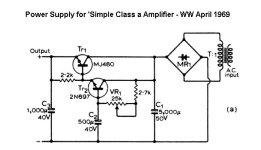
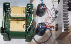
I also decided to use this device so that I could use higher voltage transformers, I have an unused 27 volt secondary transformer, so I decided to make an electronic filter circuit for it that could work on a high-rated capacitance.
Also, this solution makes it possible to avoid isolating the power mosfet drain from the cooling radiator, which is fixed to the chassis of the case and connected to the GND.
electronic filter circuit:
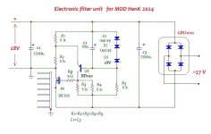
it is also a stabilizer; the voltage can be selected either by a zener diode or by the number of diodes in the D1D2 circuit.
The electronic filter-stabilizer is assembled using resistors of equal value, except for the resistor in the power Mosfet gate.
Later I’ll try to use, for example, the more powerful IRF1018 instead of the power mosfet IRF620.

I also decided to use this device so that I could use higher voltage transformers, I have an unused 27 volt secondary transformer, so I decided to make an electronic filter circuit for it that could work on a high-rated capacitance.
Also, this solution makes it possible to avoid isolating the power mosfet drain from the cooling radiator, which is fixed to the chassis of the case and connected to the GND.
electronic filter circuit:


it is also a stabilizer; the voltage can be selected either by a zener diode or by the number of diodes in the D1D2 circuit.
The electronic filter-stabilizer is assembled using resistors of equal value, except for the resistor in the power Mosfet gate.
Later I’ll try to use, for example, the more powerful IRF1018 instead of the power mosfet IRF620.
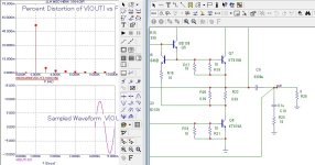
Hennady, an interesting improvement to such a well-known scheme. I have not yet analyzed its work in detail, but I would like to ask you - are the distortion figures given measured data or obtained using a simulator? It would be interesting to see the level and spectra of distortion at various output signal levels - from minimum to maximum (one step before the clipping occurs).
According to the diagram and measurements, everything is very simple - there was a video where a person measured distortions and spectra in real time in the laboratory, all parameters, all harmonics and their level were visible, there was also a dependence of the growth of harmonics on the output power, in the original version at the input amplitude voltage +/-9 volts at a load of 8 ohms at 1 kHz showed 0.4% of the second hamonics, which was also confirmed by my simulator. Having increased the maximum power due to modification - at an amplitude output voltage of +/-9 volts at an 8-ohm load, the distortion at a frequency of 1 kHz was 0.04%.Hennady, an interesting improvement to such a well-known scheme. I have not yet analyzed its work in detail, but I would like to ask you - are the distortion figures given measured data or obtained using a simulator?
spectra with dominance of the second harmonic, the clip is symmetrical.It would be interesting to see the level and spectra of distortion at various output signal levels - from minimum to maximum (one step before the clipping occurs).
I am currently optimizing the design of cooling radiators, because... The temperature of the radiators above 52 degrees also affects the sound quality - i.e. While additional cooling is required (fan), the radiator is still being completed; in the convection form, the flat surface does not provide the necessary heat removal, so we make a U-shaped design of the radiators, and there is already a positive result.
Those. the result will be the optimal value of the radiator area and its design features to use only passive convection type of cooling.
I didn't find this video in the thread. In addition, it is not clear which circuit it refers to - you write that you modified the circuit. I would ask you, if possible, to provide more detailed information on distortion at several output power levels and indicate whether this is measured data or obtained in the simulator.According to the diagram and measurements, everything is very simple - there was a video where a person measured distortions and spectra in real time in the laboratory
And another question - is it possible to use KT819 in the output stage and how much will this worsen the parameters of the amplifier?
Where did I say that the video is in the topic?I didn't find this video in the thread.
What exactly is not clear? circuit clone of the original topology from 1969.In addition, it is not clear which circuit it refers to - you write that you modified the circuit.
data of course from simulator, I did not indicate anywhere that this was measured data. We were talking about measurements after manufacturing the amplifier; so far only the manufacturing process is underway.this is measured data or obtained in the simulator.
Will it be clear like this (see attachment) or does something need to be explained?is it possible to use KT819 in the output stage and how much will this worsen the parameters of the amplifier?
I don't really trust the simulation results. They are usually overpriced. In practice, other results may be obtained due to deviations in the parameters of the components used and other unaccounted factors.
I hope that after production you will carry out extensive measurements of this amplifier.
I hope that after production you will carry out extensive measurements of this amplifier.
you are writing nonsense, the question is not in trust but in understanding the results, the original model is simulated, and a modified version is simulated on the same parts, the result is compared. If the result of a modification in a model is superior to the original, what should this mean?I don't really trust the simulation results.
Any other part or use of a similar transistor from another manufacturer is essentially a modification. The results will always be “different”, because... A radio amateur can use a different layout inside the case, a transformer with different current-voltage characteristics and different acoustics. And it’s very good that this does not stop radio amateurs from pursuing their favorite hobby...In practice, other results may be obtained due to deviations in the parameters of the components used and other unaccounted factors.
This is not a scientific work and there is no purpose to conduct extensive research, which you probably hope in your heart. If you don't have faith, then good luck...I hope that after production you will carry out extensive measurements of this amplifier.
We are talking about different things - you are talking about comparing two circuits in a simulator, and here you are right. And I’m talking about achievable parameters, about their absolute and not relative values. And here the simulation can (and often does) give overestimated parameters.you are writing nonsense, the question is not in trust but in understanding the results, the original model is simulated, and a modified version is simulated on the same parts, the result is compared. If the result of a modification in a model is superior to the original, what should this mean?
Whether or not to take any measurements is your decision. But if they exist, it increases confidence in the design.This is not a scientific work and there is no purpose to conduct extensive research, which you probably hope in your heart. If you don't have faith, then good luck...
How hard it is to communicate when you repeat the same thing twice. “noch einmal” - There are hardware measurements that I saw in the video of distortion of 0.4% (second harmonic) of the original (clone) at 1 kHz with a load of 8 ohms at an output voltage of +/-9 volts, I enter the model and get 0.4% of the second harmonic on the same parameters , further modification.... What other "trust" is there?And I’m talking about achievable parameters, about their absolute and not relative values. And here the simulation can (and often does) give overestimated parameters.
Last edited:
I don’t understand why you answer so irritably. I'm trying to make sense of the information you posted on four pages of discussion and I didn't see the video you watched, so I'm asking questions.
By the way, have you thought about adding a small resistor to the Q8 emitter?
By the way, have you thought about adding a small resistor to the Q8 emitter?
Last edited:
because issues of faith are not within the scope of this topic. and then, do you see a ready-made amplifier for measurements? I don’t, moreover, the theoretical calculation of a convection radiator does not solve the problem of heat compensation, heating the radiator to more than 47 degrees degrades the performance of any transistor-based amplifier; heating to more than 52 degrees, the effect of temperature can already be heard in speaker systems. Therefore, until the construct is ready, it is better not to ask about measurements and do not hope that they will occur earlier than necessary.
I saw this video about seven years ago, and I remember all the nuances of hardware measurements about this amplifier....I didn't see the video you watched,
it is not needed there, it will reduce the efficiency of the lower transistor, namely, it will reduce its current, because of which, in order to compensate for the current up to 1 A, you will have to pass 1.5 times more current through the driver transistor Q2, which is why its open loop gain will drop and the distortion at the output will increase by at least 2 times.By the way, have you thought about adding a small resistor to the Q8 emitter?
without this resistor, the transistor is stable in current, the temperature gradient is negative, the driver transistor is not overloaded.
Last edited:
Finally, after much listening and 8 options for a set of compensation elements, I settled on what seemed to me the best in terms of subjective perception of sound.
The amplifier produces a slightly unusual sound, I would say an ambient sound.
The issue with temperature has also been resolved - in this design it is not necessary to make the current higher than 1 Ampere, because the power drops and it begins to sound less “light and powerful”...
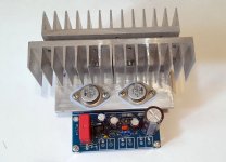
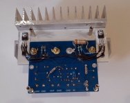
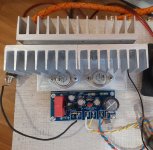
With a current consumption of 1A and 28 volts of power supply for the amplifier, a convection cooling radiator of 900-1000 cm2 is sufficient. For Q5Q3 you need a separate radiator, I used a 300 cm2 radiator. which is secured together with a detachable heatsink for power transistors through thermally insulating gaskets.
According to the scheme :
It is with this circuit that the second channel will be completed and installed in the housing. A stabilizer on the Mosfet circuit will be used, which is available earlier in the topic. The voltage block will be 1 to 2 channels, (no dual mono).
Modification result:
diagram in attachment:

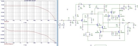
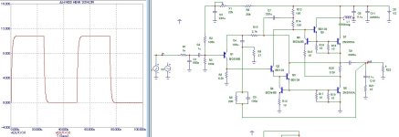
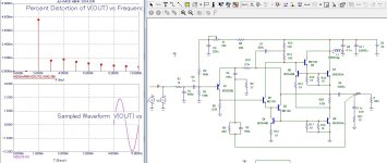
The amplifier produces a slightly unusual sound, I would say an ambient sound.
The issue with temperature has also been resolved - in this design it is not necessary to make the current higher than 1 Ampere, because the power drops and it begins to sound less “light and powerful”...
With a current consumption of 1A and 28 volts of power supply for the amplifier, a convection cooling radiator of 900-1000 cm2 is sufficient. For Q5Q3 you need a separate radiator, I used a 300 cm2 radiator. which is secured together with a detachable heatsink for power transistors through thermally insulating gaskets.
According to the scheme :
- R1С1 - frequency filter 225 kHz
- gain Q1 open loop 24dB
- gain Q2 open loop 40dB
- pole above 20kHz
- the value of capacitor C4 has been reduced to 100 μF so that it does not affect the phase distortion below 20 Hz, the cutoff frequency from below is now 10 Hz, i.e. 1 octave lower than 20 Hz, which is good.
- setting the Current or increasing it can be done by selecting resistor R20, you can simply solder an equal value of Resistor in parallel, a lower resistance corresponds to an increase in current
- X1 - configures symmetrical signal limiting at a frequency of 1 kHz. (approximately X1+15 kOhm = 28 kOhm).
It is with this circuit that the second channel will be completed and installed in the housing. A stabilizer on the Mosfet circuit will be used, which is available earlier in the topic. The voltage block will be 1 to 2 channels, (no dual mono).
Modification result:
- minimal changes to the original version
- ultralinearity preserved
- increased output power
- it became possible to use speaker systems with an impedance of 4 ohms without increasing the current.
- good transient response
- less dependence of sound on the set current
- less thermal load on the amplifier elements
diagram in attachment:


Last edited:
Let's evaluate the contribution of the stabilizer and rectifier capacitors to minimize the ripple voltage to power the amplifier.
The need to reduce supply voltage ripple is associated with the possibility of obtaining low distortion at the first watt, in our case this is 0.005% distortion percentage.
I typed a stabilizer circuit and a rectifier connection circuit with a load equivalent to the load of 2 amplifier channels.
As a result, the stabilizer reduced ripple by 11.5 dB for two amplifier channels.
Let's try to reduce this level of pulsation, to be continued....
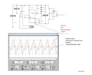

Last edited:
Of all the possible options, without significantly complicating the circuit, increasing efficiency is to increase the capacitance in the base of the bipolar transistor from 100 uF to 330 uF (see attachment). This allows the stabilizer to reduce the level of supply voltage ripple by 20 dB when feeding through it 2 channels of amplifiers in class A at once.
If anyone has any ideas, please suggest them, we can check what the result might be.
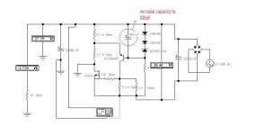
If anyone has any ideas, please suggest them, we can check what the result might be.

Last edited:
Hi all!
Today I decided to finish the issue with compensation, because... a capacitor shunting a negative feedback resistor is not compensation in general terms, because This capacitor makes the feedback resistor frequency dependent at high frequencies and load impedance, and its presence also increases sensitivity to the wires that connect the speaker systems.
Therefore, I decided to completely redo the compensation.
Because we have a cascade of transistors Q3 Q4 Q7 is a controlled current load for transistor Q8 it is logical to use a “current compensation bridge”, the circuit for this compensation looks like this:

The figure shows the formulas for calculating the compensation capacitor C5.
You can also see that I rebuilt 2 nodes in the amplifier

this current communication circuit P8 is now taken from Collector Q2, the reason is to reduce the current modulation when operating the stage Q3 Q4 Q7 to the input stage through the emitter Q1, the base current Q3 is sufficient to stabilize the operating point at the output of the amplifier.
Changing the current feedback connection point made it possible to use the R3R4 divider to form a symmetrical operating point, which will not depend on the supply voltage and current setting of the power transistors. Thus, there is no need to adjust the operating voltage at the amplifier output; it will be set automatically regardless of the supply voltage level.
C4 with a nominal value of 330 uF returned to its place, after changing the point of connection of the current feedback, phase distortions at infra-low frequencies no longer appear and increasing this capacitance significantly reduces distortions in the mid-frequency band.
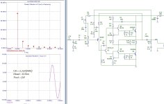
The circuit is assembled and now it reproduces for me - everything sounds very good, clean and powerful, and this is the result for distortion:
Please note this distortion is at a frequency of 20 kHz, where the influence of the compensation bridge is maximum.
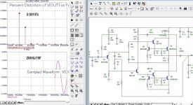
Such a small diagram, but so many modifications)))
Today I decided to finish the issue with compensation, because... a capacitor shunting a negative feedback resistor is not compensation in general terms, because This capacitor makes the feedback resistor frequency dependent at high frequencies and load impedance, and its presence also increases sensitivity to the wires that connect the speaker systems.
Therefore, I decided to completely redo the compensation.
Because we have a cascade of transistors Q3 Q4 Q7 is a controlled current load for transistor Q8 it is logical to use a “current compensation bridge”, the circuit for this compensation looks like this:
The figure shows the formulas for calculating the compensation capacitor C5.
You can also see that I rebuilt 2 nodes in the amplifier
this current communication circuit P8 is now taken from Collector Q2, the reason is to reduce the current modulation when operating the stage Q3 Q4 Q7 to the input stage through the emitter Q1, the base current Q3 is sufficient to stabilize the operating point at the output of the amplifier.
Changing the current feedback connection point made it possible to use the R3R4 divider to form a symmetrical operating point, which will not depend on the supply voltage and current setting of the power transistors. Thus, there is no need to adjust the operating voltage at the amplifier output; it will be set automatically regardless of the supply voltage level.
C4 with a nominal value of 330 uF returned to its place, after changing the point of connection of the current feedback, phase distortions at infra-low frequencies no longer appear and increasing this capacitance significantly reduces distortions in the mid-frequency band.
The circuit is assembled and now it reproduces for me - everything sounds very good, clean and powerful, and this is the result for distortion:
Please note this distortion is at a frequency of 20 kHz, where the influence of the compensation bridge is maximum.

Such a small diagram, but so many modifications)))
Last edited:
- Home
- Amplifiers
- Solid State
- Hennady's take on the 1969 JLH
