I will propose this modification of the output stage. Up to 9 watts operates in class A, is not sensitive to low-impedance loads, the output transistors operate without thermal overheating, the circuit characteristics are stable, the operating point is also more stable, the distortion spectrum up to 10 watts consists of only one second harmonic, closer to the maximum output power it increases slightly "tail" of even harmonics,
sine wave limitation is symmetrical.
with a power greater than 9 watts, the output stage operates in class AB with symmetrical (not to be confused with complementary) control.
This modification allows you to unload the current of the driver transistor Q9, and make its operation less dependent on the complex load impedance, i.e. Q9 began to work in a more linear mode than in the original version. Also, the output transistors received symmetrical control of the base current. with a power greater than 9 watts, the input stage operates in class AB with symmetrical (not to be confused with complementary) control.
compensation capacitor C8 appeared due to the fact that the input capacitances of oldschool slow/slow transistors no longer affect the frequency parameters of the driver transistor Q9.
Q9 received freedom !!!)))
The depth of negative feedback increased by 7dB and remained the same linear as in the original circuit.
Last edited:


It is easy to see that the JLH circuit does not change - this is an option for the possibility of using for modern high-quality low-impedance acoustic systems for this circuit. I intentionally did not put the denominations, anyone interested can write in a personal message.that is not the JLH anymore,
The addition of "R extra" is necessary so that the capacitor in the NFB circuit does not litter when playing sound.
Although if someone likes to listen to the influence of nonlinearity of components and a complex acoustic system, then yes, let it remain as it is.
Modifications would suggest that improvements can be made after all!
For what it is worth trawling through some old simulations with changed models suggest that the output stage alone generates about 0.6% THD with TIP35's and 0.9% with MJ15022. Of course this will reflect on the models used. The TIP35 model seems basic, but shows a slightly higher gain at higher currents than the MJ15022 although the worst case spec. could be worse, and to make matters more confusing the typical gain of the TIP35 published by ONSemi is almost double. You could be lucky with TI35/BD249 or unlucky.
THD with the driver stage included was 1.2% for the TIP35 and similar at 0.96% with the MJ15022. (By itself, open loop).
The input stage device on the other hand operates at about 350uA and swings up and down by 180uA which generates a lot of second harmonic.
One option is to increase the current in the stage and reduce the emitter resistor and feedback to keep the closed loop gain the same. Overall THD for a TIP35 operating at 1.7A and +/-10V supply into 4 ohms reduced from 0.3 to 0.2%. Not great.
On the other hand the original JLH simulated with MJL3281A's into 4 ohms with as Hennady suggested an increased emitter resistor (330 ohms) indicated 0.014%. At 4 ohm load and 1kHz.
It is worth remembering that JLH's original article showed the lowest THD with 15 ohm loads.
My recommendation, should you dig up past posts, is to use the newer device types. What I was suggesting with the TIP35 is that it would be reasonable (and consistent with the original article) for 4 ohm loads, not that it was the best choice.
For me, this stage has already been passed; the components that are now on the market do not correct the insufficient current for controlling the bases of the output stage. Therefore, all the curvature of this simple design appears with a decrease in the load impedance, and with the capacitive nature of the load, the amplifier becomes simply curved.My recommendation, should you dig up past posts, is to use the newer device types. What I was suggesting with the TIP35 is that it would be reasonable (and consistent with the original article) for 4 ohm loads, not that it was the best choice.
what are we talking about then?It is worth remembering that JLH's original article showed the lowest THD with 15 ohm loads.
P.S. here is my view before modifications
There is no desire to assemble the JLH a second time according to the old scheme, because there is no required quality.
Attachments
Last edited:
Actually, saying the same thing I think. Lower load impedances place a greater demand on the output current which increases non-linearity, which I take it is what you mean by curvature. And in JLH's original article, he seemed to overlook that as he merely suggested various component selections for 4, 8 or 15 ohms loads.what are we talking about then?
I agree that the basic JLH really isn't the best which is why newer transistors give it a better response, but even better results can be achieved with additional modifications.
Though modifying too much moves away from JLH.
which is why newer transistors give it a better response,
This stage has also been passed - the result was also not pleasing
Here modern output transistors in the output stage:

the result is like “head against the wall.”
the circuit JLH appeared long before the understanding of current control of a bipolar transistor for a low-resistance load. There is no point in clinging to the old.
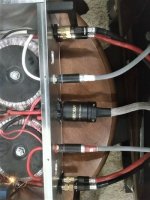
Four transistors per output stage? It is not a surprise that there is a lot of base-emitter capacitance to charge/discharge which the basic JLH (without a driver) would struggle.
The little springs on the emitters I assume are supposed to be resistors, but would have some inductance whether or not they are resistors.
The little springs on the emitters I assume are supposed to be resistors, but would have some inductance whether or not they are resistors.
Modern transistors are used, the total capacity of which is less than one double pair of old-school transistors that were in the original version.Four transistors per output stage? It is not a surprise that there is a lot of base-emitter capacitance to charge/discharge which the basic JLH (without a driver) would struggle.
These are 0.1 ohm wire resistors, they are needed to balance parallel pairs, the effect of their inductance is an exaggerated fantasy, because they influence less than the influence of wires connected to the speaker system.The little springs on the emitters I assume are supposed to be resistors, but would have some inductance whether or not they are resistors.
It is clear that parallelling transistors needs emitter resistors to distribute the current evenly.
I was not unduly concerned about the audio effect of a small inductance, but whether there is an influence on the stability at high frequencies.
Unless the windings are non-inductive, my observation (which may be wrong) is that they are 6 turns of about 6mm diameter and 12mm long, which I would estimate has an inductance of around 150nH.
If so that would have a higher impedance than 0.1 ohms over 150kHz, which may affect stability as these are inside the feedback loop, while speaker cables are outside.
It was not meant as a criticism, I should have been clearer on my concern. I question whether they are as low as 1.8nH. If really, then there would be very little effect, I agree.
Your concern would be justified if the amplifier had a high slew rate and high output power, then yes, with sharp current surges through these resistors, the negative effect of their parasitic inductance appears.
However, in fact, in the original circuit the slew rate is only 2.4 V/µs - this is slower than the “turtle” even if it is greatly frightened. )))
The reason for the low speed is still the same - the input of the power transistor.
However, in fact, in the original circuit the slew rate is only 2.4 V/µs - this is slower than the “turtle” even if it is greatly frightened. )))
The reason for the low speed is still the same - the input of the power transistor.
Well, the original circuit using 2N3055H type devices indeed had a slow slew rate. Using epitaxial base devices with ft's in the 4MHz region may have a problem with stability. I did not say will, it is just a possibility. Could be even worse with 30MHz devices.
And were the emitter resistors really 1.8nH?
And were the emitter resistors really 1.8nH?
I’ll try to use a practical example to convince you that with 3055 in this scheme you can get good slew rate.Well, the original circuit using 2N3055H type devices indeed had a slow slew rate.
you can calculate it yourself: for 10 ohms of the same resistor with a power of 5 watts, the value from the specification is indicated as 0.36 μH.And were the emitter resistors really 1.8nH?
and if I remember correctly, I soldered them bifilarly - on one pair of transistors in one direction, on the second in the other.
although I’m not very sure that’s how I soldered them, because stilt that this cannot be of decisive importance, that’s not what bothered me in this project.
P.S. non-inductive resistors needed for high-frequency devices with a frequency of 30-50 MHz and higher, why discuss this in low-frequency devices?
Last edited:
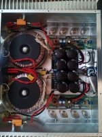
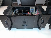
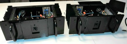
Look what I just bought.
Way cheaper than I could make them.
They use 2n3773, they will be come out and replaced with better ones, the old blue Phillips caps will go to, the pots will be replaced with 20 turn, and the output capacitor will also go, have some nice Siemens sikorel to take their place, I just fell in love with them.
Attachments
This is the square wave at the output of the amplifier in the original, see pictures, with a load of 8 ohms and the modification option - intentionally reduced the load to 4 ohms. output transistors 2N3055 both models of the original circuit and in a modified one.Well, the original circuit using 2N3055H type devices indeed had a slow slew rate.
I equalized the input voltage and output power of these two versions for comparison


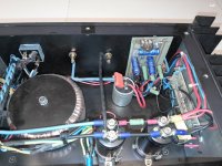
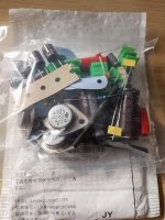
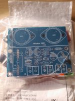
The board for one channel is ready from a set to a modified version.
It was necessary to cut only 2 tracks: one for the input RC - LP filter, and the second for the current sensor.
Next, the board will be mounted on the radiator - the power transistors will be placed on the radiator
.
It was necessary to cut only 2 tracks: one for the input RC - LP filter, and the second for the current sensor.
Next, the board will be mounted on the radiator - the power transistors will be placed on the radiator
.


- Home
- Amplifiers
- Solid State
- Hennady's take on the 1969 JLH